 Yarisworld
When I was reading his post about using a torque wrench to loosen a bolt, all I could think was "somebody's dad is gonna be PISSED"Originally Posted by Sir A.Y. Atoyot ↑If you were really using a torque wrench as a breaker bar, you should know that this is a bad practice - it could make the torque wrench inaccurate (at least), or even destroy it.
Can we do this? (aka The DIY Cruise Control Thread)
498 posts · 380,332 views · page 5 of 10
Replies continued
The more I read, the less i want to do this lol Maybe if someone does it and gets it right with a good diy...
That's what I'm saying now :) I might wait and finish after someone smarter than me does it and includes nice pics to follow haha!
Ditto for me. I have the 09 and bought the OEM stalk, but mine's a 5 spd. so I'm worried about the clutch switch install
Originally Posted by nickhjort ↑Ok...so the first test didn't go so hot. I have some pics...
So I started the car and the airbag light was on...duh...I don't have the passenger side plugged in. I pulled out the driveway nice and easy so as not to tip over my speedometer. I hit 40mph and press that "on" button...pop! There goes a fuse and all my dash lights start coming on and the "cool" light is blinking, and the car is boggin down. It didn't stall, but it wouldn't go faster. SO I pulled over and started checking fuses. My 7.5A Ignition fuse blew. Now I'm not sure if something crossed or what. I checked and double checked all my connections. Not bare wires, nothin'. I changed the fuse and everything was fine...safe to say I didn't try testing it again on the way home :)
Here's what I did:
I tapped the #40 pin on the ECM connector "A21" and ran the wire through the firewall and spliced it with the red wire from the switch setup.
Then I took a jumper...with a fuse... and jumped from the blue wire CTScott showed me in the engine compartment fuse box, but the white wire wasn't where it should be, but it was just to ground it. So I jumped it to another white wire that grounded (according to my multimeter touching the white wire and the frame...0 resistance) Anyway, I have no idea why it tripped the ingnition fuse. Please help me with any ideas. I hope i didn't fcuk up the ECM by blowing the fuse. Everything seemed perfectly fine when I replaced it. HELP! :(
I think your in the wrong pin on the ECU:
This is the Wire harness side view looking into the connector from the pins:
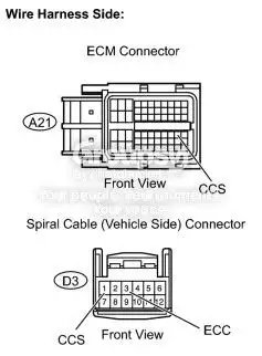
I think you're mirror imaged across the center divider:
Picture lost · i236.photobucket.com
Oh, and the white that you jumper the clutch switch wire to is indeed the one I meant, so you're OK there...
Ok i see that now that I look at the pic. You had one more white one in with the brown one huh? And I see I was looking at the wrong side of the connector...duh. Anyway I'm gunna try that other pin in the ecm and try again tomorrow. Thanks a lot we'll see what happens :)
Sorry about the confusion on that. I didn't realize until I dropped the pic on the computer that the white I meant was hidden and the other white was right there in the foreground.Originally Posted by nickhjort ↑Ok i see that now that I look at the pic. You had one more white one in with the brown one huh? Anyway I'm gunna try that other pin in the ecu and try again tomorrow. Thanks a lot we'll see what happens :)
I was just tracing the 7.5A IGN fuse and I think that the pin you are on, on the ECM, is hot, so when you hit the switch it grounded it and popped the fuse, as that fuse feeds parts of the ECM.
By the way, before you road test with the correct pin, try the ON button in the driveway to be safe. I can hit the on with the ignition on and engine off and the cruise light comes on. Obviously you won't be able to tell if cruise is actually working, but at least you'll know if you pop a fuse.
I think that you identified #40 correctly on your first picture, but got turned around somehow with the plug - I could be wrong, but I think that you inserted your jumper in #29.Originally Posted by nickhjort ↑Ok...so the first test didn't go so hot. I have some pics...
So I started the car and the airbag light was on...duh...I don't have the passenger side plugged in. I pulled out the driveway nice and easy so as not to tip over my speedometer. I hit 40mph and press that "on" button...pop! There goes a fuse and all my dash lights start coming on and the "cool" light is blinking, and the car is boggin down. It didn't stall, but it wouldn't go faster. SO I pulled over and started checking fuses. My 7.5A Ignition fuse blew. Now I'm not sure if something crossed or what. I checked and double checked all my connections. Not bare wires, nothin'. I changed the fuse and everything was fine...safe to say I didn't try testing it again on the way home :)
Here's what I did:
I tapped the #40 pin on the ECM connector "A21" and ran the wire through the firewall and spliced it with the red wire from the switch setup.
Then I took a jumper...with a fuse... and jumped from the blue wire CTScott showed me in the engine compartment fuse box, but the white wire wasn't where it should be, but it was just to ground it. So I jumped it to another white wire that grounded (according to my multimeter touching the white wire and the frame...0 resistance) Anyway, I have no idea why it tripped the ingnition fuse. Please help me with any ideas. I hope i didn't fcuk up the ECM by blowing the fuse. Everything seemed perfectly fine when I replaced it. HELP! :(
Yes, yes people it's all coming together now. I did get turned around and had it in pin 29, not pin 40. I couldn't wait till tomorrow, got my flash light and just cruised the town without touching the gas pedal :) It works! I did test the button just before I left, and the fuse didn't pop. So my second road test was a success. Thank you all for your help and if anyone else with the 07 liftback is gunna do this I can try to help as much as I can. Running wires all the way to the ECM is a pain in the arse, but it's totally worth it. If anyone needs anymore pictures let me know and I'll try to take them tomorrow.
All I need to do now is find out a way to make my LED light up when it's on. And run wires for the clutch switch which I will be buying later this week. Any input on that would be greatly appreciated.
Picture lost · i236.photobucket.com
All I need to do now is find out a way to make my LED light up when it's on. And run wires for the clutch switch which I will be buying later this week. Any input on that would be greatly appreciated.
Picture lost · i236.photobucket.com
Awesome! I'll design a circuit for the LED. It will probably require changing the on/of switch to a DPDT switch, as the LED circuit will have to be controlled by the switch, rather than the ECM.
Thanks for being the guinea pig - this will certainly help me install in my '08.Originally Posted by nickhjort ↑Yes, yes people it's all coming together now. I did get turned around and had it in pin 29, not pin 40. I couldn't wait till tomorrow, got my flash light and just cruised the town without touching the gas pedal :) It works! I did test the button just before I left, and the fuse didn't pop. So my second road test was a success. Thank you all for your help and if anyone else with the 07 liftback is gunna do this I can try to help as much as I can. Running wires all the way to the ECM is a pain in the arse, but it's totally worth it. If anyone needs anymore pictures let me know and I'll try to take them tomorrow.
All I need to do now is find out a way to make my LED light up when it's on. And run wires for the clutch switch which I will be buying later this week. Any input on that would be greatly appreciated.
You don't think the wires going to the speedo and stuff has the cruise wire in it even though I don't have cruise indicator...? That would be much easier :)
Unfortunately not. The microcontroller for the combination meter gets the cruise status from the ECM over the CAN bus.Originally Posted by nickhjort ↑You don't think the wires going to the speedo and stuff has the cruise wire in it even though I don't have cruise indicator...? That would be much easier :)
The only possibility that I can see is that the microcontroller appears to drive all of the status LEDs via a 4-bit multiplexer. It is possible that the micro is programed to support the LED, but has not connection to it. If you want to disassemble your meter and take some pictures of the PCB I can take a look.
I can take some pics tomorrow. You need the back or front of the circuit board? I might see how hard it's gunna be to change the led's while I'm at it. Change the colors of my speedo and stuff.
Both sides if you can get at them. If not, some good macros of the IC's so I can figure out what they are and the pinouts of them.Originally Posted by nickhjort ↑I can take some pics tomorrow. You need the back or front of the circuit board? I might see how hard it's gunna be to change the led's while I'm at it. Change the colors of my speedo and stuff.
Damn, thanks for doing all this $hit man. I'll get the pics for ya tomorrow.
Hmm I am old enough to be a dad lol ... and don't worry, it's a cheap-o one from crappy tire that has a metal 'needle' bar that you can easily bend back. I don't care if it breaks or not, I just needed a long breaker bar type deal, and since breaker bars here are ~$30, it was cheaper to buy a $9 torque wrench for the same deal.Originally Posted by supmet ↑When I was reading his post about using a torque wrench to loosen a bolt, all I could think was "somebody's dad is gonna be PISSED"
The circuit needs to be a bistable flip-flop.Originally Posted by PK198105 ↑Scott why not just take an OR gate and use that for the LED. Or a simple 2N2222 transistor setup as a switch.
Alright, so to make the OEM stalk work, how would it be different than what nickhjort is doing?
The only difference will be that instead of ending up at his switches, your two wires will end at the stalk. Everything else is identical.Originally Posted by mrbond ↑Alright, so to make the OEM stalk work, how would it be different than what nickhjort is doing?
What about the extra wires I need? Any particular gauge or material?
Also - would I go about threading the wires through the steering wheel via the clockspring wiring?
And on the stalk, which wire is which? I have a lot of questions because the majority of this thread was about adding buttons for cruise control, and the stalk was only talked about at the very beginning.
Also - would I go about threading the wires through the steering wheel via the clockspring wiring?
And on the stalk, which wire is which? I have a lot of questions because the majority of this thread was about adding buttons for cruise control, and the stalk was only talked about at the very beginning.
Originally Posted by mrbond ↑What about the extra wires I need? Any particular gauge or material?
Also - would I go about threading the wires through the steering wheel via the clockspring wiring?
And on the stalk, which wire is which? I have a lot of questions because the majority of this thread was about adding buttons for cruise control, and the stalk was only talked about at the very beginning.
I would go with somewhere between 18 and 22 gauge. Insulation material is not critical.
The wires are already in the clockspring, so you will just plug in the stalk connector when you pull off the steering wheel.
On the other end of the spiral cable (at the connector shown below, next to the yellow one) you don't have the blue and brown wires in pins 1 (blue) and 3 (brown), so you will either have to find pins that fit, or solder the wires right to the connector's pins.
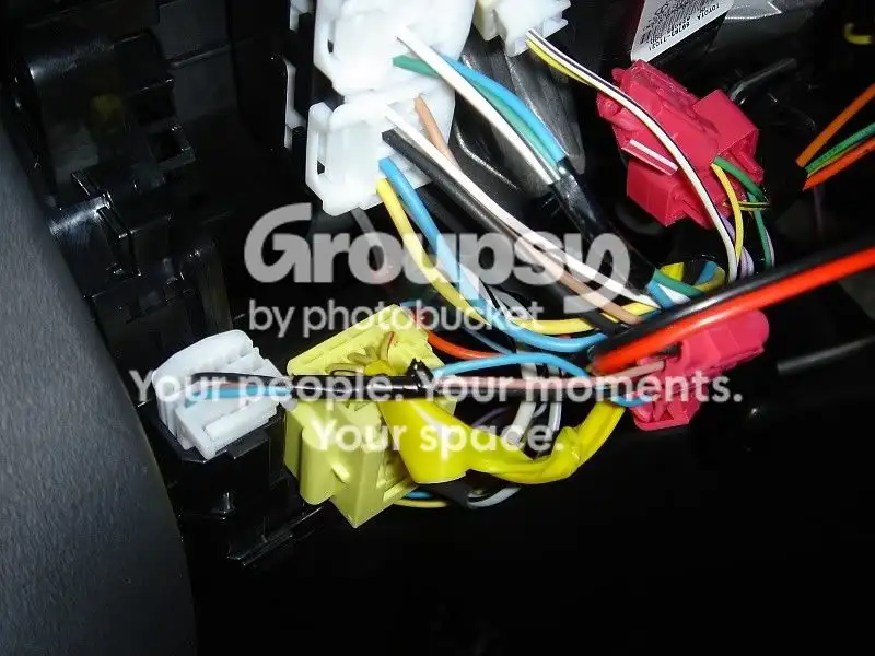
I'm definitely missing something. Where do the additional 2 wires from D3 go? I mean, with the switch method for models other than the 09, it seems like you don't need to use D3. But since I'm going to be using the stalk, I need to use D3.
The connector above is D3. If you use the switch method for 08, then you go straight from the ECM to the switches.Originally Posted by mrbond ↑I'm definitely missing something. Where do the additional 2 wires from D3 go? I mean, with the switch method for models other than the 09, it seems like you don't need to use D3. But since I'm going to be using the stalk, I need to use D3.
For the stalk method the wire from pin 40 of the ECM goes where the blue wire is above in D3. Where the brown wire is in D3, you will run a wire from that position to a ground point.
And I wouldn't need to bother with the clutch control switch then?
You would still need the cruise clutch switch (if your car is MT). It connects from the clutch switch (which you would have to add) on the pedal bracket to the under hood fuse box. It is separate from the stalk and its wiring.Originally Posted by mrbond ↑And I wouldn't need to bother with the clutch control switch then?
Here's those pics CTScott...hope they are good enough. If you need more I can take more tomorrow. I'm heading to work right now...
Picture lost · i236.photobucket.com
Picture lost · i236.photobucket.com
Picture lost · i236.photobucket.com
Picture lost · i236.photobucket.com
Picture lost · i236.photobucket.com
Picture lost · i236.photobucket.com
Picture lost · i236.photobucket.com
Picture lost · i236.photobucket.com
\Picture lost · i236.photobucket.com
Picture lost · i236.photobucket.com
Picture lost · i236.photobucket.com
Picture lost · i236.photobucket.com
Picture lost · i236.photobucket.com
Picture lost · i236.photobucket.com
Picture lost · i236.photobucket.com
Picture lost · i236.photobucket.com
Picture lost · i236.photobucket.com
Picture lost · i236.photobucket.com
Picture lost · i236.photobucket.com
Sorry there's so many on this post, but I figured the more the better :) Let me know what you think. Like I said before, I feel pretty confident in my basic electrical abilities. I can solder to PCB's and all that fun stuff. I would rather not switch the switches around (since I just got them all done and looking good), but however I can get that light to light up I'll do it. Oh and also I have a 12V LED in there right now, only cause I had a bunch laying around. Let me know if I need a different voltage LED too. Thanks again.
And I hope all this stuff is helping other people want to do this mod. I've spent less than $10 so far. $500 or $10...no brainer 👍
Picture lost · i236.photobucket.com
Picture lost · i236.photobucket.com
Picture lost · i236.photobucket.com
Picture lost · i236.photobucket.com
Picture lost · i236.photobucket.com
Picture lost · i236.photobucket.com
Picture lost · i236.photobucket.com
Picture lost · i236.photobucket.com
\Picture lost · i236.photobucket.com
Picture lost · i236.photobucket.com
Picture lost · i236.photobucket.com
Picture lost · i236.photobucket.com
Picture lost · i236.photobucket.com
Picture lost · i236.photobucket.com
Picture lost · i236.photobucket.com
Picture lost · i236.photobucket.com
Picture lost · i236.photobucket.com
Picture lost · i236.photobucket.com
Picture lost · i236.photobucket.com
Sorry there's so many on this post, but I figured the more the better :) Let me know what you think. Like I said before, I feel pretty confident in my basic electrical abilities. I can solder to PCB's and all that fun stuff. I would rather not switch the switches around (since I just got them all done and looking good), but however I can get that light to light up I'll do it. Oh and also I have a 12V LED in there right now, only cause I had a bunch laying around. Let me know if I need a different voltage LED too. Thanks again.
And I hope all this stuff is helping other people want to do this mod. I've spent less than $10 so far. $500 or $10...no brainer 👍
Excellent pics! Let me scratch around them a bit and see what I can come up with.
Definitely watching. I hate doing electrical work, so waiting on another dummy like me to attempt it. Or a nice DIY wrote up. 👍Originally Posted by nickhjort ↑And I hope all this stuff is helping other people want to do this mod. I've spent less than $10 so far. $500 or $10...no brainer 👍
Great work so far guys.
Well I'm your dummy ryank! 😆👍
And Thanks for scratching around CTScott. My car is all put back together for now, so I won't get a chance to work on it again till this weekend. In the meantime, lemme know what you think about the LED. Thanks a million!
And Thanks for scratching around CTScott. My car is all put back together for now, so I won't get a chance to work on it again till this weekend. In the meantime, lemme know what you think about the LED. Thanks a million!
Originally Posted by CTScott ↑Excellent pics! Let me scratch around them a bit and see what I can come up with.
OK. To figure this out, we'll need the meter PCB to be hooked up to the car. What you'll have to do is turn the ignition on, and initially take 16 voltage measurements, then press your cruise on button and take the 16 again. If one of the 16 changes after turning cruise on, we'll know that that pin would drive the cruise LED if the car had one.
IC500 and IC501 are the "8 bit shift registers". Each of them can drive 8 LEDs. We need to look at pins 3 through 6 and 11 through 14 on each.
Pin 1 is the pin under the "1" after the IC50x label. In your picture which has the text upside down, Pin 3 is right above the middle of the 00 in IC500 and right above the 1 in IC501. In that view, 4, 5 and 6 are to the right of 3.
Pin 9 is at the top right in that view (next to the upside down 9). Pin 11 is two pins to the left of 9. 12, 13, and 14 are to the left on 11.
So, connect it up, turn the ignition switch on, and measure from a ground point to each of those 16 pins. They will measure ~0.5 VDC, or ~5.0 VDC.
Then, press your cruise on button and measure all 16 again.
If I'm using the OEM stalk method on an '09, is it just plug & play? I know I need the cruise control clutch switch but I'm wondering if there are any other wires/connections I need to make to get it working.
No - That's it. For an 09 AT, it's just mount and plug in the stalk and you're done. For 09 MT, same plus mount and plug in the clutch switch. No running of any additional wires on either.Originally Posted by MGargano ↑If I'm using the OEM stalk method on an '09, is it just plug & play? I know I need the cruise control clutch switch but I'm wondering if there are any other wires/connections I need to make to get it working.
Originally Posted by PK198105 ↑Ok i did a bit of scratching on my own, btw great pics of the meter, i think i killed two birds with one stone. First it is my belief that the 07 meters are not even programmed for cruise because there is not even a connector for the LED and no trace for it either. you do not have a tach am i correct Nick? therefore the icon should be under the speedo needle to the right of it and from the pics i see none. So Scott i don't think that checking the shift registers will do anything if the controller doesn't have the program that will allow it to send the signal to the icon.
Second some of you may remember this i was trying to figure out a way to switch from metric to mph and vice versa, well thanks to your pics Nick i came to the conclusion that this also is not possible to "hack", I read the Repair manual Meter section and the only way to switch this is through the Intelligent tester.
here is the list of things that can be Customized through the intelligent tester:
Display (Item) Default Contents Setting
KEY REMIND SOUND SLOW Changes key reminder buzzer
intervals FAST / NORMAL / SLOW
LIGHT REMIND ON Turns light reminder buzzer ON
and OFF ON / OFF
SEAT BELT WARN D/P ON Turns seat belt warning buzzer
ON and OFF D/P ON / D ON / P ON / D/P OFF
UNITS BY REGION Different for every region Changes drive monitor display
units
KM/L JP / KM/L / ML/G US / ML/
G UK / KM/G
I realize that the LED is not there and that there is a good chance that the microcontroller is not programmed to support the cruise LED, but two days ago I would have said the same for the ECM, when he found that the wire didn't exist in pin 40, and the cruise clutch switch wiring didn't exist.
I say check the shift register output for the heck of it, as I don't believe that all 16 outputs are in use.Originally Posted by PK198105 ↑so what do we do?
Just as a side note, I think it would be worthwhile if a mod re-named this thread to something like "DIY Cruise Control how-to, 2007-2009".
The current thread title won't be helpful in future searches :D
The current thread title won't be helpful in future searches :D
Is there a DIY for mounting/wiring the clutch switch? I haven't gotten it yet so I'm not even sure what it looks like/where to put it.Originally Posted by CTScott ↑No - That's it. For an 09 AT, it's just mount and plug in the stalk and you're done. For 09 MT, same plus mount and plug in the clutch switch. No running of any additional wires on either.
Take a look at this DIY on installing cruise on a Matrix. It shows the Clutch Switch installation:Originally Posted by MGargano ↑Is there a DIY for mounting/wiring the clutch switch? I haven't gotten it yet so I'm not even sure what it looks like/where to put it.
http://matrixowners.com/index.php?ac...r&f=23&t=71247
Looks like the plug for this switch should already be hanging somewhere under the dash, if I'm reading this correctly. Seems pretty straight forward.Originally Posted by CTScott ↑Take a look at this DIY on installing cruise on a Matrix. It shows the Clutch Switch installation:
http://matrixowners.com/index.php?ac...r&f=23&t=71247
Correct. Plug is hanging there. Remove bolt, screw in switch, plug in connector.Originally Posted by MGargano ↑Looks like the plug for this switch should already be hanging somewhere under the dash, if I'm reading this correctly. Seems pretty straight forward.
Alright you guys, I'm home and I used my Cruise Control to and from work...it was GREAT! Definatly worth the trouble. But of course right now it's kind of a pain to always be wondering "Did I turn it on yet? Is it on or off right now? I sure wished this LED worked." :)
I just got done reading all these replies. I will definatly take the meter apart again and check all those pins "just for the heck of it," cause it will be nice if that works out. But if not we'll have to figure something else out.
PK198105, no I don't have the tach in the combination meter, but I did install one aftermarket...I think that doesn't effect this process. And I do also see many empty solder points on the PCB...LED's, IC's and some other stuff.
Also, I didn't see the clutch switch wire hanging down under the dash, but I will search again just to make sure.
Anyway, I probably won't have any time to do this until saturday, so hang in there guys and I will keep checking in here everyday to see what's shakin'. I will post more pics on saturday with my results from the voltage tests. Thanks guys!
I just got done reading all these replies. I will definatly take the meter apart again and check all those pins "just for the heck of it," cause it will be nice if that works out. But if not we'll have to figure something else out.
PK198105, no I don't have the tach in the combination meter, but I did install one aftermarket...I think that doesn't effect this process. And I do also see many empty solder points on the PCB...LED's, IC's and some other stuff.
Also, I didn't see the clutch switch wire hanging down under the dash, but I will search again just to make sure.
Anyway, I probably won't have any time to do this until saturday, so hang in there guys and I will keep checking in here everyday to see what's shakin'. I will post more pics on saturday with my results from the voltage tests. Thanks guys!
Originally Posted by nickhjort ↑Alright you guys, I'm home and I used my Cruise Control to and from work...it was GREAT! Definatly worth the trouble. But of course right now it's kind of a pain to always be wondering "Did I turn it on yet? Is it on or off right now? I sure wished this LED worked." :)
I just got done reading all these replies. I will definatly take the meter apart again and check all those pins "just for the heck of it," cause it will be nice if that works out. But if not we'll have to figure something else out.
PK198105, no I don't have the tach in the combination meter, but I did install one aftermarket...I think that doesn't effect this process. And I do also see many empty solder points on the PCB...LED's, IC's and some other stuff.
Also, I didn't see the clutch switch wire hanging down under the dash, but I will search again just to make sure.
Anyway, I probably won't have any time to do this until saturday, so hang in there guys and I will keep checking in here everyday to see what's shakin'. I will post more pics on saturday with my results from the voltage tests. Thanks guys!
Sounds good. I have a circuit design in my back pocket for making the LED work, without changing to a dual pole switch, in case we need it...
Nice.
Any ideas on where I can find a steering column cover that already has the opening for the cruise stalk? My car's basically brand new and I don't wanna mess up the OEM cover if I can help it.
Anybody know the part #?Originally Posted by PK198105 ↑try a scrap yard. you might get lucky and find one there if not there is always the dealership
i thought the cruise came through the steering wheel, not the column cover?
Cover, Steering Wheel Boss, Lower: 45184-52130-B0
This is for one that has factory cruise control, (and it is the plastic back of the wheel, not the column cover).
This is for one that has factory cruise control, (and it is the plastic back of the wheel, not the column cover).
Ohh so it's actually the back of the steering wheel, not the column cover? Doh! This fits & color matches the US 09?
Yes.Originally Posted by MGargano ↑Ohh so it's actually the back of the steering wheel, not the column cover? Doh! This fits & color matches the US 09?