Replies continued
CTScottUSA, CT · Mar 16, 2010#151 Originally Posted by
lily ↑ well, still no cruise yet.
my main question is about how to take off the ECU harness.
i have gone as far as "unlocking" the harness via the "white clip" like the pictures from the previous posts.
but does the harness come off even further??? <<< can someone please take a pic of the "full breakdown" of the harness???
what i did was pretty much just "unlocked" the harness via the "white clip" and slid a wire through PIN 40. <<< this i believe somehow is not "good enough" contact to the ECU itself.
i think this is what I'm stuck on, because i cannot establish a good contact from the wire to the ECU. i have the little connector pin, but just don't know how to break down the ECU harness to fit it onto PIN 40 of the harness.
HELP PLEASE.
I just put together a quick DIY on removing the connector, pulling the plug, and inserting the pin:
DIY - How to remove or insert a pin on the ECM Connector A21 Originally Posted by
lily ↑ well, still no cruise yet.
i think this is what I'm stuck on, because i cannot establish a good contact from the wire to the ECU. i have the little connector pin, but just don't know how to break down the ECU harness to fit it onto PIN 40 of the harness.
HELP PLEASE.
Lily,
I think the one thing which no one has explicitly stated yet is that you MUST have the special Toyota "repair terminal" to make this mod work for the 07-08 models. Just shoving any ole wire through the pin 40 hole doesn't cut the mustard. Did anyone get it to work that way?
Originally Posted by
goat1of2 ↑ Lily,
I think the one thing which no one has explicitly stated yet is that you MUST have the special Toyota "repair terminal" to make this mod work for the 07-08 models. Just shoving any ole wire through the pin 40 hole doesn't cut the mustard. Did anyone get it to work that way?
A few people have done it with the "ole wire" method. It certainly can work that way, but will be more prone to stop working and to potentially let moisture get to where it shouldn't.
thank you CTScott for the write up.
i will give it another try this coming weekend and report back.
tune in...
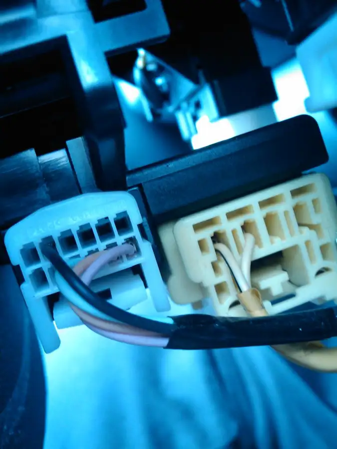
fratzicaBucharest · Mar 17, 2010#155So this is what I found under the steering column in my EU spec 08` Yaris D-4D.
I have the brown and blue wires but both in the wrong pin locations.
Sorry for the blueish color, i took the photos with my cellphone.
Originally Posted by
fratzica ↑ So this is what I found under the steering column in my EU spec 08` Yaris D-4D.
I have the brown and blue wires but both in the wrong pin locations.
Sorry for the blueish color, i took the photos with my cellphone.
Those are for the steering wheel radio controls.
Damn...
I really need the cruise control function because I drive a lot outside town and I get tired of holding the accelerator pedal at a certain speed. Probably got used to the cruise control because my last car had this function. Just yesterday i drove almost 1000 km or 620 miles and had to take a 1 hour nap on the return trip. I know 620 miles is not a lot in the US due to your highway system, but in my country we have only 2 (yes, two) highways, most of the roads having one lane for each direction only.
Anyway.. I`ll try to find a cheaper solution :)
Thank you Scott for your help!
CTScottUSA, CT · Mar 17, 2010#158 Originally Posted by
fratzica ↑ Damn...
I really need the cruise control function because I drive a lot outside town and I get tired of holding the accelerator pedal at a certain speed. Probably got used to the cruise control because my last car had this function. Just yesterday i drove almost 1000 km or 620 miles and had to take a 1 hour nap on the return trip. I know 620 miles is not a lot in the US due to your highway system, but in my country we have only 2 (yes, two) highways, most of the roads having one lane for each direction only.
Anyway.. I`ll try to find a cheaper solution :)
Thank you Scott for your help!
You might want to contact the company in the link below. They are based in Denmark and make cruise control kits for various vehicles that can even use the OEM cruise control stalk. They definitely make one for the Auris D-4D, so they should have one for the Yaris D-4D as well.
http://www.el-pas.com/products_ecruise.htmJust sent them an e-mail. Fingers crossed :D
CTScottUSA, CT · Mar 17, 2010#160 Originally Posted by
fratzica ↑ Just sent them an e-mail. Fingers crossed :D
Here's another potential option; I believe that The Rostra cruise control kit, which is used as the dealer added cruise control on US Yaris, would work as well.
I just noticed in the EWDs for the D-4D, that the wiring to the accelerator pedal (connector A20) is the same as for our US cars. The Rostra kit connects to the accelerator pedal connector, the neutral safety switch (AT) or tach wire (MT), the vehicle speed sensor wire, and the brake switch. So, I think it would work fine on your D-4D.
Here's a place that sells the Rostra kits for $249:
http://www.thecruisecontrolstore.com...g/X380183/0003thecruisocontrostore.com ships only in the US and Canada.. Let`s see what the people from el-pas.com say.
weaver615New York · Mar 19, 2010#162Ok Guys I tried this MOD today and it doesn't work. I used 2 NO Switches and 1 680ohm 1/2 5% cfr resistor, grounded to chasis at the drivers side door and hot to PIN 40 of the ECM. Jumpered the Clutch switch and took it for a test drive. NADA.
I'm wondering if the resistor may be the problem or if the problem could be that I used 20 Gauge solid and not stranded wire, (shouldn't make a difference I wouldn't think), to build the circuit and run the hot and ground. every thing checked and doubled checked, any Ideas? BTW, I am using the 2 switch method not the 4.
CTScottUSA, CT · Mar 19, 2010#163 Originally Posted by
weaver615 ↑ Ok Guys I tried this MOD today and it doesn't work. I used 2 NO Switches and 1 680ohm 1/2 5% cfr resistor, grounded to chasis at the drivers side door and hot to PIN 40 of the ECM. Jumpered the Clutch switch and took it for a test drive. NADA.
I'm wondering if the resistor may be the problem or if the problem could be that I used 20 Gauge solid and not stranded wire, (shouldn't make a difference I wouldn't think), to build the circuit and run the hot and ground. every thing checked and doubled checked, any Ideas? BTW, I am using the 2 switch method not the 4.
How did you make the connection to pin 40?
Solid vs stranded shouldn't make a difference, but with the 680 ohm resistor being near the top end of the range (567-693 ohms), if your 5% tolerance is off in the + direction, then you may be out of range for the set function. +5% on 680 puts you up to 714 ohms.
I made the connection direct to PIN 40 on the ECM. Ran positive wire thru firewall to the ECM pushed out the rubber block and fed the wire down til it came out the other side and trimmed it as close to the connector as possible. Put the wire shield back on and re-connected the ECM....Should I try using 2 - 330ohm resistors they are a quarter watt but the wattage shouldn't make that much of a difference I don't think should it?
CTScottUSA, CT · Mar 19, 2010#165 Originally Posted by
weaver615 ↑ I made the connection direct to PIN 40 on the ECM. Ran positive wire thru firewall to the ECM pushed out the rubber block and fed the wire down til it came out the other side and trimmed it as close to the connector as possible. Put the wire shield back on and re-connected the ECM....Should I try using 2 - 330ohm resistors they are a quarter watt but the wattage shouldn't make that much of a difference I don't think should it?
Since you are using a wire, rather than the connector pin, make sure that the connection is good. You can measure the voltage at the other end of that wire and with the ignition on it should be 12V.
For the resistor(s), 1/4 watt is fine (even 1/8 watt would be fine, as the current draw is negligible).
Whatt would you suggest? Leave the wires as they are and cut at the switches and rebuild the circuit then splice back into the wires already ran, I would rebuild it using a radioshack 560 ohm 1/2W 5% Carbon Film Resistor. Or, should I just tear everything out and start fresh, new circuit, new wires, etc. Thanks for the help I really appreciate it. I want Cruise soo bad!!!! lol
weaver615New York · Mar 19, 2010#167Would it be safe to leave the clutch jumpered until I can buy the acutal switch from the dealer? I know I would have to be careful NOT to push the clutch down until after I disengaged the cruise.
CTScottUSA, CT · Mar 19, 2010#168 Originally Posted by
weaver615 ↑ Whatt would you suggest? Leave the wires as they are and cut at the switches and rebuild the circuit then splice back into the wires already ran, I would rebuild it using a radioshack 560 ohm 1/2W 5% Carbon Film Resistor. Or, should I just tear everything out and start fresh, new circuit, new wires, etc. Thanks for the help I really appreciate it. I want Cruise soo bad!!!! lol
You could rebuild it and splice it back in.
Originally Posted by
weaver615 ↑ Would it be safe to leave the clutch jumpered until I can buy the acutal switch from the dealer? I know I would have to be careful NOT to push the clutch down until after I disengaged the cruise.
It is, as long as you do remember.
Originally Posted by weaver615 ↑
ok Scott I'm gonna try to rebuild the circuit and splice it back in. The 560 ohm 1/2w resistor with 5% CFR would be ok right? It would put me at 588 ohms almost at the middle of the scale but better than 714 ohms. Another thing I just noticed is the switches I bought Radioshack catalog #: 275-644 don't say whether they are NO or NC, Would these switches Radioshack catalog #: 275-1566, be better? I know they have to be NO switches, just wondering if that could be the problem I got NC instead of NO switches.
A 560 is probably too low. The 5% can go either way, so if you use a resistor close to either end, you really should check it with an ohm meter to verify what the actual value is. Being within the range is critical. If you are out of band, the ECM will not recognize the function.
The 275-644 switches are N.O., so they are fine.
ok I checked my NEW switch and have 12 volts at the circuit end of the run wires with the ignition in the "on" position, so I have a connection to the ECM. Still nada. I'm stumped.
I'm thinking I should use 2- 330 ohm resistors, that would put with in the band +/- 5%.
CTScottUSA, CT · Mar 19, 2010#172Did you check the actual resistance of your resistor?
weaver615New York · Mar 19, 2010#173Scott, just replaced risistors with 2 330 ohm resistors, still nada, resistance at 630 well with in the band...I am perplexed....now what?
CTScottUSA, CT · Mar 20, 2010#174 Originally Posted by
weaver615 ↑ Scott, just replaced risistors with 2 330 ohm resistors, still nada, resistance at 630 well with in the band...I am perplexed....now what?
Take pictures of everything - Switch wiring, clutch switch bypass wiring, ECM connection point.
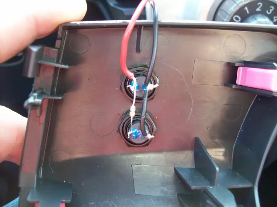
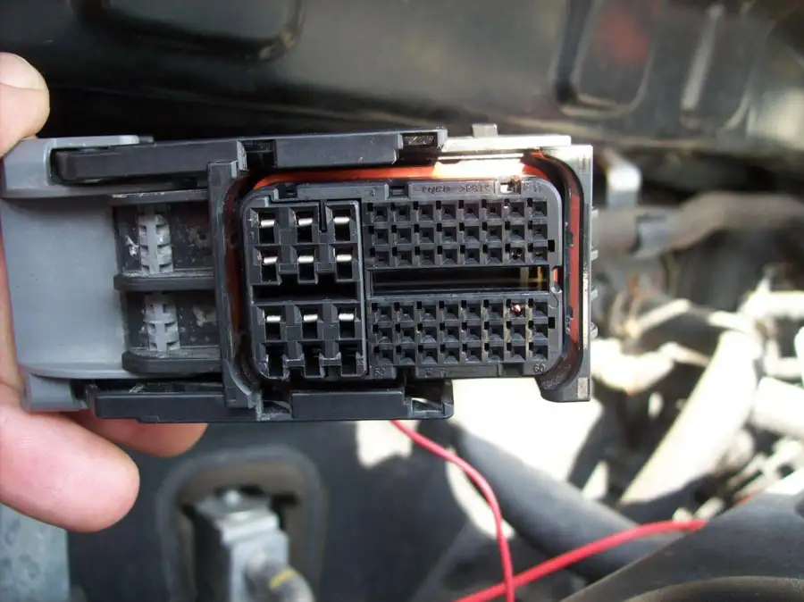
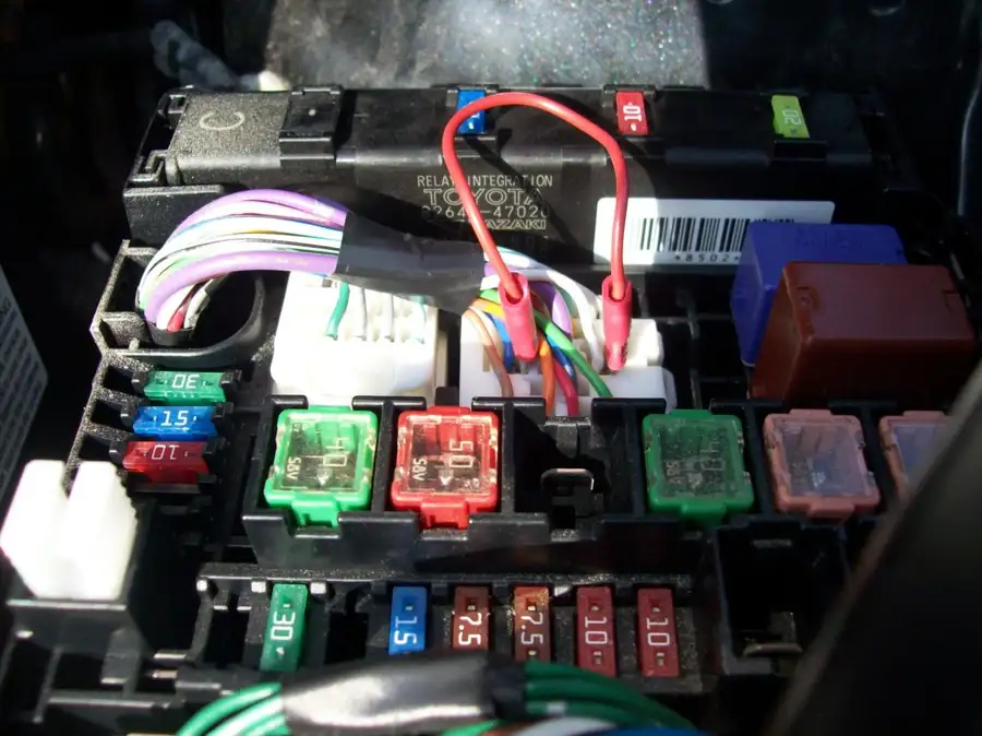
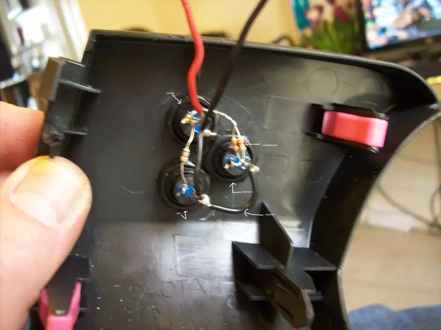
ok here are pics of my DIY cruise control on a 2007 Yaris 5 speed Manual transmission.
PIC 1: switch with circuit Used 680 ohm resistor. Splice in place after redoing circuit. Red wire to PIN 40 on ECM Black wire to ground at drivers side door.
PIC 2: ECM with Red wire at PIN 40.
PIC 3: Clutch jumpered at fuse box done using nickhjort's method.
PROBLEM: Cruise doesn't work. ON/OFF swtich doesn't seem to get power. SET doesn't engage.
HYPOTHESIS: Either bad switches (second set), or ECM doesn't support Cruise Control.
Where do I go from here? 🤷
On the ECM you have the correct position.
The clutch switch bypass is in the correct position.
The switches look fine. In the pic the top one is on/off and the bottom one is set.
With the ignition on, if you measure from the red to the black wire on the top switch, what do you see for voltage?
weaver615New York · Mar 20, 2010#177Voltage with ignition in on position Almost 13 volts (analog meter here). With Ignition off 0 (zero) volts.
CTScottUSA, CT · Mar 20, 2010#178And, if you press the top switch it goes to 0 volts?
weaver615New York · Mar 20, 2010#179Yupper goes to Zero Volts. BTW< the resistor I used is the 680 Ohm resistor from radioshack that you get in the $12.99 package of resistors.
CTScottUSA, CT · Mar 20, 2010#180OK. How about the clutch switch bypass - Do you have definite contact between the connector pins and your jumper? With the ignition on, both the blue and white wire terminals should measure 12 V.
weaver615New York · Mar 20, 2010#181HALLELUJAH!!! I have Cruise Control...CTScott, that's what the problem was. The Clutch bypass wasn't at 12 volts...once I moved things around a little and got them to get 12 volts I took the car out for a test drive and WAH LAH!!! Instant cruise control...I thank you ever so much for helping me with this, you are awesome!!!! How can I repay your help?
CTScottUSA, CT · Mar 20, 2010#182Excellent!
weaver615New York · Mar 20, 2010#183Now I just have to get the real clutch bypass switch....I'll call my local dealer Monday and see if I can order one.....Thanks again...I'm TOTALLY Stoked now!!!
weaver615New York · Mar 23, 2010#184UPDATE: DIY Cruise Control working fine. CTScott, I was wondering if would be possible to add JUST a RESUME switch to the 2 switch method? I was driving to work today and got to wondering this....Is it possible?
CTScottUSA, CT · Mar 23, 2010#185 Originally Posted by
weaver615 ↑ UPDATE: DIY Cruise Control working fine. CTScott, I was wondering if would be possible to add JUST a RESUME switch to the 2 switch method? I was driving to work today and got to wondering this....Is it possible?
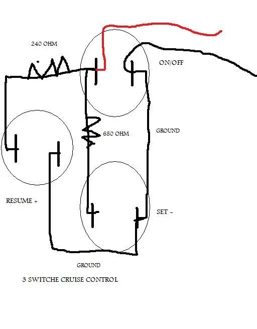
Sure - That would be the 3 switch method...
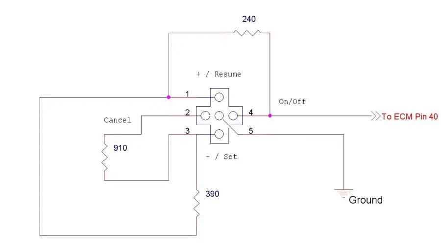
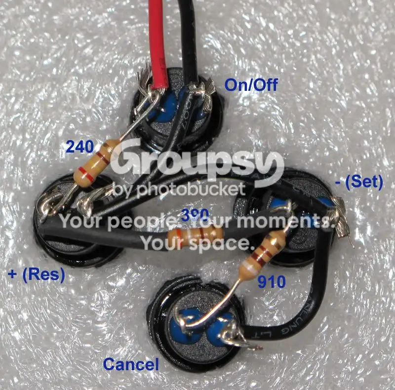
If you look at the picture below, from my original DIY, if you added a third switch, you would gain resume (and would then have + and -, since they are secondary functions on the set and resume switches)
You could parallel it to your existing rig using a 240 ohm resistor, or redo your switch wiring and just leave off the cancel switch.
The 3 switch DIY criuse control would be wired like this I believe. Am I correct in assuming this is right? Please excuse the art work...I did this in Paint so it isn't the greatest.
Originally Posted by
weaver615 ↑ The 3 switch DIY criuse control would be wired like this I believe. Am I correct in assuming this is right? Please excuse the art work...I did this in Paint so it isn't the greatest.
Correct
ok now...i need some help.
well, i've installed a wire with the connector tip, into PIN 40 of the ECU harness.
i've also made the 2-button style controller, just as the illustrations from the previous posts.
and...still no avail.
i have tested out the on/off buttons with a DMM and it reads about 5.24 when pressed and the ignition turned to 'on'. having the key to 'on' and no pressing the button, i get 0 on the DMM.
I NEED HELP TROUBLESHOOTING!
i think that the wire into PIN 40 is not contacting inside the ECU or the buttons are no good. i have the radio shack 275-1548 SPST 'Mini' buttons with a 125 VAC, 0.3amp @ 50 VDC. <<< ARE THESE BUTTONS GOOD ENOUGH TO MAKE THIS WORK???
i've already checked the single resistor to be about 634. <<< Is this OK?
out of ideas no, HELP!!!
CTScottUSA, CT · Mar 26, 2010#189 Originally Posted by
lily ↑ ok now...i need some help.
well, i've installed a wire with the connector tip, into PIN 40 of the ECU harness.
i've also made the 2-button style controller, just as the illustrations from the previous posts.
and...still no avail.
i have tested out the on/off buttons with a DMM and it reads about 5.24 when pressed and the ignition turned to 'on'. having the key to 'on' and no pressing the button, i get 0 on the DMM.
I NEED HELP TROUBLESHOOTING!
i think that the wire into PIN 40 is not contacting inside the ECU or the buttons are no good. i have the radio shack 275-1548 SPST 'Mini' buttons with a 125 VAC, 0.3amp @ 50 VDC. <<< ARE THESE BUTTONS GOOD ENOUGH TO MAKE THIS WORK???
i've already checked the single resistor to be about 634. <<< Is this OK?
out of ideas no, HELP!!!
The switches are your issue. Those are normally closed (N.C.) switches, so they act like they are pressed until you press them, then they act like they are not. Radio Shack does not do a good job with labeling their switches.
You need normally open (N.O.) ones. 275-1571 are mini N.O. ones for example.
AH HA!!!!!!!!!!!!!!!
upon further 'inspecting' the descriptions on the baggy, it does indeed say (in very fine print) "N.C. contacts". <<< I assume this is the "normally closed" which i need "normally open".
tomorrow i will have to go get the ones stated then.
i appreciate the help CTScott.
tune in...
lilyMN · Mar 27, 2010#191well...i went and got two different buttons (radio shack part number: 275-0644).
installed it and IT WORKS!!!
YAY...THANKS TO CTScott and others for their pics.
turned out that i had the wrong buttons this whole time. when i initially went to buy the buttons, i swore i thought i saw them as "N.O." but i guess i was reading too fast and was rushing it.
thanks again, now with cruise, its a breeze on them long road trips.
happy driving!!!
CTScottUSA, CT · Mar 27, 2010#192 Originally Posted by
lily ↑ well...i went and got two different buttons (radio shack part number: 275-0644).
installed it and IT WORKS!!!
YAY...THANKS TO CTScott and others for their pics.
turned out that i had the wrong buttons this whole time. when i initially went to buy the buttons, i swore i thought i saw them as "N.O." but i guess i was reading too fast and was rushing it.
thanks again, now with cruise, its a breeze on them long road trips.
happy driving!!!
Nice! I'm always glad to hear the success stories.
CTScott I have the +Res wired per the scematic I put above. Tested and it disconnects the Cruise. I had to use 2 - 120 resistors. Should those be 120K resistors to get 240? I have 120's and 120K's
weaver615New York · Mar 27, 2010#194Here is a pic of what I have now.
Wow, that's one blurry picture!
OK. You are close - It's two 120's not 120K's (which would be 120,000), so you have the correct values. The problem is that they are in parallel instead of series. They need to be end to end to make 240, not side by side.
weaver615New York · Mar 27, 2010#196Got it...Re-did them putting them in Series, and all works great now, I thought that was what I did wrong but wasn't sure. Thanks again CTScott 'You da man'!!!!! 🙇
Now what should my next Mod be???
yongtaufooUSA · Apr 4, 2010#197Hi guys,
Im trying to install cruise controls for my Yaris (Automatic Transmission) and would like to get some advice from the experts here before proceeding with my DIY:
My ECM A21-40 has a 12V with ignition on. So now all i need to do is to connect the cruise control stalk CCS pin to A21-40 and ECC pin to ground correct?
Do i need to do any other modifications for cruise control to work?
Thanks!! 🙂
CTScottUSA, CT · Apr 4, 2010#198 Originally Posted by
yongtaufoo ↑ Hi guys,
Im trying to install cruise controls for my Yaris (Automatic Transmission) and would like to get some advice from the experts here before proceeding with my DIY:
My ECM A21-40 has a 12V with ignition on. So now all i need to do is to connect the cruise control stalk CCS pin to A21-40 and ECC pin to ground correct?
Do i need to do any other modifications for cruise control to work?
Thanks!! 🙂
That's it for an Auto.
Originally Posted by
CTScott ↑ That's it for an Auto.
Hi Scotts,
Thank you so much for your reply. 🙂
But im puzzle about another thing. If referring to the cruise control switch schematic, turning cruise control ON-OFF will short ECM Pin40 12V to ground. Will I then damage my ECM by doing this since it is outputing a 12V? And ECM Pin40 is an input or output port?
Thanks!
One more CC done! Thanks to CTScott and all who contributed. A suggestion if you have the TB upgrade: you will need to disconnect the battery while doing this DIY so the ECM resets. Only disconnecting the one plug causes the initial ocillation to return. For some reason it won't learn until you completely reset the ECM.
I want to pass on a couple of 680 ohm resistors that I was given to anyone who needs them. You only need one to do the 2-button setup. PM me with an address and I'll mail one to you.
Thanks again CTScott. This was the only thing my car was missing.
 Yarisworld