Replies continued
CTScottThread starterUSA, CT · Oct 14, 2010#51 Originally Posted by
adam1981 ↑ Right now from what I can remember this is what else I need :
Headlights (I have a low current neg headlight output)
Door Triggers and type (have pos and neg trigger wires)
Also have aux outputs for various things such as remote window roll up...would be great if I found where to tap the windows up.
Oh, I have a Prestige APS-997N...
Headlights: No low current tap, (~5A for low beams) - negative trigger, sky blue wire in pin 8 of headlight stalk connector.
Door triggers (negative input when door is open):
FL-red wire 4A-21, FR-light blue wire 4A-24, RL-green wire 4A-5, RR-light blue wire 4A-20, Trunk/Hatch- Sky blue wire 4A-7
If the alarm only has one input for the 2 or 4 doors, you can tap all wires together.
Auto window up/down module install:
Dual auto down power windows? Originally Posted by
CTScott ↑ Headlights: No low current tap, (~5A for low beams) - negative trigger, sky blue wire in pin 8 of headlight stalk connector.
Door triggers (negative input when door is open):
FL-red wire 4A-21, FR-light blue wire 4A-24, RL-green wire 4A-5, RR-light blue wire 4A-20, Trunk/Hatch- Sky blue wire 4A-7
If the alarm only has one input for the 2 or 4 doors, you can tap all wires together.
Auto window up/down module install:
Dual auto down power windows?
Yeah, it said I would prob have to use a relay on the lights.
You are awesome! Thanks! Hopefully I can get these last few connections in tomorrow.
Originally Posted by
CTScott ↑ Headlights: No low current tap, (~5A for low beams) - negative trigger, sky blue wire in pin 8 of headlight stalk connector.
Door triggers (negative input when door is open):
FL-red wire 4A-21, FR-light blue wire 4A-24, RL-green wire 4A-5, RR-light blue wire 4A-20, Trunk/Hatch- Sky blue wire 4A-7
If the alarm only has one input for the 2 or 4 doors, you can tap all wires together.
Auto window up/down module install:
Dual auto down power windows?
4A is the top left harness on that main panel behind the pull out pocket right?
All the wires match up except Green Pin 5 is Yellow on mine and There is nothing in Pin 20; there is a Blue in 19...
With the windows...do I have to have this additional module? The way my manual reads it will do auto-up without any additional modules... Can I just tap the Up Motor wires on that chart?
Also, something else I noticed, my horn is not sounding when it should with use of RS/Alarm. I tapped the wire under the column like your document said... It is negative switching right?
I need to get you a 6-pack for all this help! 👍
Originally Posted by
adam1981 ↑ 4A is the top left harness on that main panel behind the pull out pocket right?
All the wires match up except Green Pin 5 is Yellow on mine and There is nothing in Pin 20; there is a Blue in 19...
With the windows...do I have to have this additional module? The way my manual reads it will do auto-up without any additional modules... Can I just tap the Up Motor wires on that chart?
Also, something else I noticed, my horn is not sounding when it should with use of RS/Alarm. I tapped the wire under the column like your document said... It is negative switching right?
I need to get you a 6-pack for all this help! 👍
Check the 4A wires relative to this:
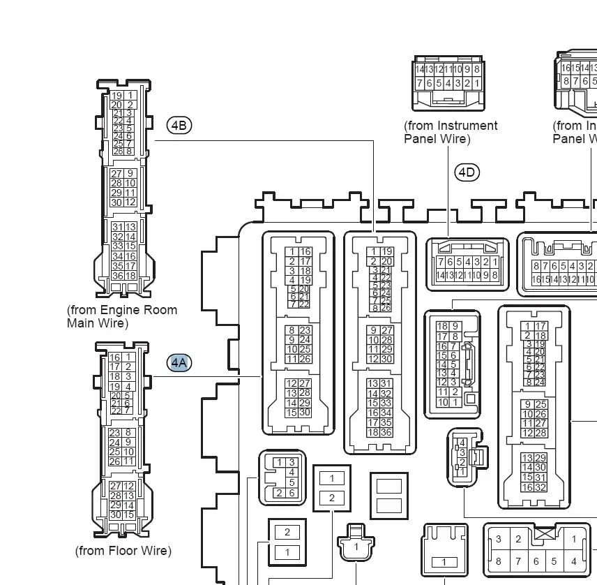
For the windows, you can use those same wires if your system has the auto roll up feature. Just make sure that it is rated for high current (20+A) or else you will need relays.
For the horn, the black wire on the spiral cable connector is definitely it, and it is definitely negative switched. Check your tap to make sure it bit all the way in.
Originally Posted by
CTScott ↑ Check the 4A wires relative to this:
Attachment 37551
For the windows, you can use those same wires if your system has the auto roll up feature. Just make sure that it is rated for high current (20+A) or else you will need relays.
For the horn, the black wire on the spiral cable connector is definitely it, and it is definitely negative switched. Check your tap to make sure it bit all the way in.
Yeap, that is the connector and the direction I was counting the terminals... So, I guess my green wire is yellow and not too sure about the discrepancy on blue 20. I will recount again, but have 4 or 5 times now...
Originally Posted by
adam1981 ↑ Yeap, that is the connector and the direction I was counting the terminals... So, I guess my green wire is yellow and not too sure about the discrepancy on blue 20. I will recount again, but have 4 or 5 times now...
OK. I just noticed you have an 08 sedan. On that 4A-5 is yellow instead of green.
I have an 08 Sedan fuse box on my test bench, and I also see the missing wire in 4A-20 (which the EWD for an 08 sedan says should be there). Those two wires are actually tied together as a single input into the ECM, so you probably only need the yellow and that is probably the reason for the lacking blue.
Originally Posted by
CTScott ↑ OK. I just noticed you have an 08 sedan. On that 4A-5 is yellow instead of green.
I have an 08 Sedan fuse box on my test bench, and I also see the missing wire in 4A-20 (which the EWD for an 08 sedan says should be there). Those two wires are actually tied together as a single input into the ECM, so you probably only need the yellow and that is probably the reason for the lacking blue.
Identified all of the wires and confirmed they are the right ones! Thanks for your continued help! However, they have proven difficult to tap because of the little slack in the harness.
So...I am going to have to connect all the door and truck triggers together. Got to thinking though, when I do this - the Driver Info Center is going to show all doors opened when only one actually is...
Do you know if I could place a diode in line with each of the taps before I tie them together to prevent the problem caused by just tying them all together - to maintain the integrity of each circuit? Will a diode pass the negative/ground provided by the switching?
Originally Posted by
adam1981 ↑ Identified all of the wires and confirmed they are the right ones! Thanks for your continued help! However, they have proven difficult to tap because of the little slack in the harness.
So...I am going to have to connect all the door and truck triggers together. Got to thinking though, when I do this - the Driver Info Center is going to show all doors opened when only one actually is...
Do you know if I could place a diode in line with each of the taps before I tie them together to prevent the problem caused by just tying them all together - to maintain the integrity of each circuit? Will a diode pass the negative/ground provided by the switching?
Yes, you can diode isolate them to keep them separate. You would tap each door wire and insert a diode between each and the door open input on the alarm. The line on the diode needs to be towards the alarm side.
Originally Posted by
CTScott ↑ Yes, you can diode isolate them to keep them separate. You would tap each door wire and insert a diode between each and the door open input on the alarm. The line on the diode needs to be towards the alarm side.
Got to browsing some of the other threads... Would there be a down side to tapping this pink wire for the door trigger for the alarm?
Think it would be a little easier than soldering in diodes...
Wires Inside the Yaris & What They Do Originally Posted by
adam1981 ↑ Got to browsing some of the other threads... Would there be a down side to tapping this pink wire for the door trigger for the alarm?
Think it would be a little easier than soldering in diodes...
Wires Inside the Yaris & What They Do
You'd have to try it with your particular alarm. Others have had issues with the alarm not liking the slow fade from ground to +12 when the doors are closed.
Hi CTScott, I got the Ultra Star 1155 and it wants two 30amp + power inputs, is there a second + I can grab inside the car?
CTScottThread starterUSA, CT · Nov 11, 2010#62 Originally Posted by
Yarisduder ↑ Hi CTScott, I got the Ultra Star 1155 and it wants two 30amp + power inputs, is there a second + I can grab inside the car?
Ignition switched or constant?
They are both marked "30amp input Constant 12volt power at ignition harness."
CTScottThread starterUSA, CT · Nov 11, 2010#64 Originally Posted by
Yarisduder ↑ They are both marked "30amp input Constant 12volt power at ignition harness."
OK - Tie both to the constant power point that I show on the under dash fuse panel. On the Yaris, everything that the remote starter is switching is low current. On some cars, the ignition switch directly switches the starter solenoid, so the remote starters have the high current feeds for that reason.
I can't seem to find a lock or unlock pulse. That connector in the kick panel doesn't provide anything... in fact I had the whole connector out and the remote locks still worked... Anyway, is there someplace else I can find a lock or unlock pulse? I prefer - but can deal with +. Thanks again.
CTScottThread starterUSA, CT · Nov 12, 2010#66 Originally Posted by
Yarisduder ↑ I can't seem to find a lock or unlock pulse. That connector in the kick panel doesn't provide anything... in fact I had the whole connector out and the remote locks still worked... Anyway, is there someplace else I can find a lock or unlock pulse? I prefer - but can deal with +. Thanks again.
Can you snap a picture of the drivers side kick plate connectors? The service manual shows GD1 and GD2 as being flipped on the sedan vs. on the liftback.
Here it is. Looks the same as in your manual.
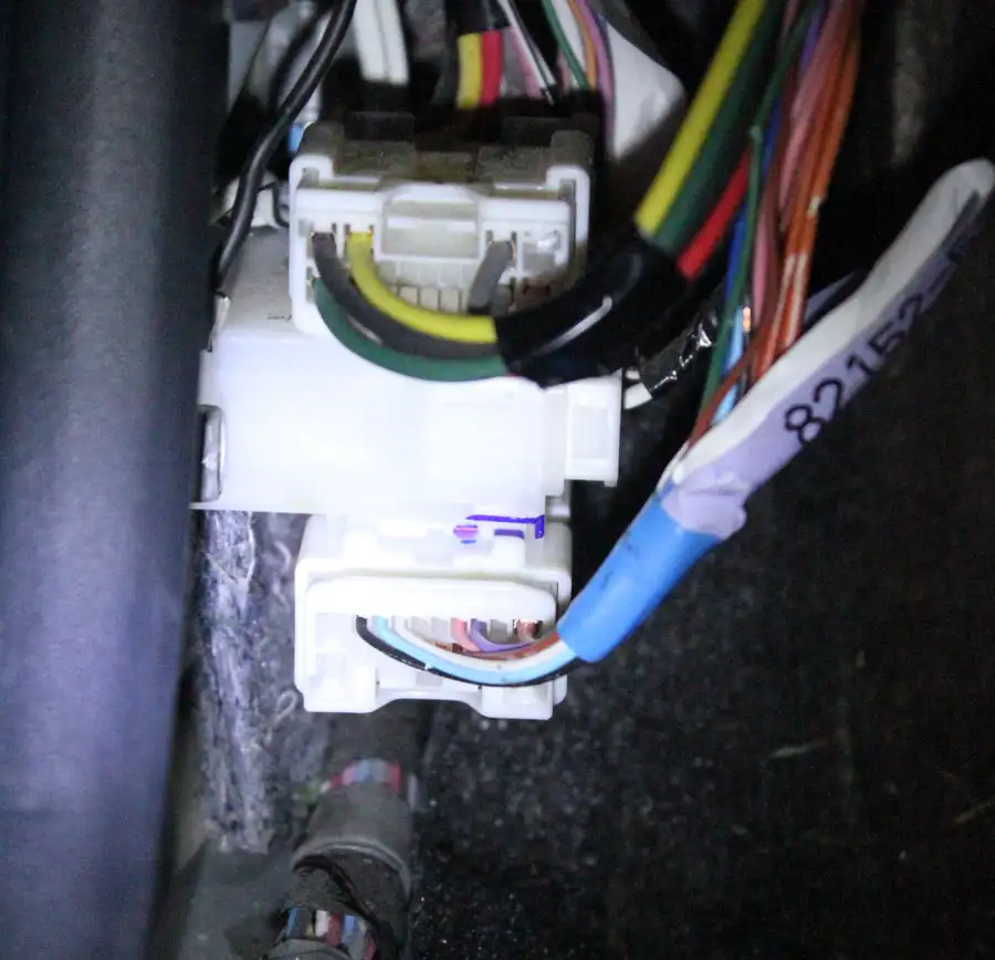
OK - looks like a misprint in the service manual (and not the first that I've run into), as that bottom connector is definitely GD1.
Measure the voltage on the blue wire on the bottom row (next to the large orange) while locking/unlocking with your keyfob. If that wire's voltage doesn't change when the lock clicks, then you may have to use the large orange (lock motor power) or pink (unlock motor power) for your lock/unlock detection.
YarisduderMontreal, Canada · Nov 12, 2010#69I the blue wire drops 1/10 of a volt when I lock/unlock. The large pink and orange wires cause my remote starter to blink the park lights incessantly, are they a + or - pulse?
YarisduderMontreal, Canada · Nov 12, 2010#70Looking at page 193 of the wiring diagrams, could I take a + pulse off connector 4H pin 8?
CTScottThread starterUSA, CT · Nov 12, 2010#71 Originally Posted by
Yarisduder ↑ Looking at page 193 of the wiring diagrams, could I take a + pulse off connector 4H pin 8?
That's basically the same as the orange wire on the kick panel (except 4H-8 is the passenger door lock motor).
By the way, take a read through page 2. Skylinecar1982 ran into some issues with the 1155 because of how the OEM remote entry works.
YarisduderMontreal, Canada · Nov 12, 2010#73I had read that a few times. It works fine with the orange or pink wires but as a + pulse. Now we need to figure out how to bi-pass the remote lock-out once the engine is started.
CTScottThread starterUSA, CT · Nov 12, 2010#74 Originally Posted by
Yarisduder ↑ I had read that a few times. It works fine with the orange or pink wires but as a + pulse. Now we need to figure out how to bi-pass the remote lock-out once the engine is started.
You might want to try disconnecting the white wire to the keyless entry receiver as I mentioned on the third page. He tried the red, but never responded about trying the white.
Is it easy to install a Avital 4111L remote start to a 2007 with no alarm system, no power windows or doors? What would be a fair price for install? I'm a lady with no knowledge on this subject. TIA
CTScottThread starterUSA, CT · Nov 14, 2010#76 Originally Posted by
miyaris ↑ Is it easy to install a Avital 4111L remote start to a 2007 with no alarm system, no power windows or doors? What would be a fair price for install? I'm a lady with no knowledge on this subject. TIA
I am not sure what an installer would charge, but for this installation on a Yaris, it should be at the bottom end of their installation fees, as it is a very easy install. Since your car is an 07, no transponder key bypass is necessary, so only the remote starter is required.
The disconnecting the white wire to the receiver does absolutely nothing. The keyless entry works in the exact same manner as if it was connected.
Looking through the various diagrams and manuals it looks to me like the CAN bus thing is involved.
CTScottThread starterUSA, CT · Nov 17, 2010#78 Originally Posted by
Yarisduder ↑ The disconnecting the white wire to the receiver does absolutely nothing. The keyless entry works in the exact same manner as if it was connected.
Looking through the various diagrams and manuals it looks to me like the CAN bus thing is involved.
It's definitely not CAN between the Main Body ECU and the Door Control Receiver. I believe it's LIN bus, which is much easier to intercept. I need to get my hands on a door control receiver to sniff that data stream.
hey ctscott.. thanks for the pdf file on the diy.. i have a question.. is there a door trigger on a 2008 yaris h/b with no power windows/locks? lmk thanks
CTScottThread starterUSA, CT · Nov 21, 2010#80 Originally Posted by
chexmix ↑ hey ctscott.. thanks for the pdf file on the diy.. i have a question.. is there a door trigger on a 2008 yaris h/b with no power windows/locks? lmk thanks
Door triggers (negative input when door is open):
FL-red wire 4A-21, FR-light blue wire 4A-24, RL-green wire 4A-5, RR-light blue wire 4A-20, Trunk/Hatch- Sky blue wire 4A-7
If the alarm only has one input for the 2 or 4 doors, you can tap all wires together.
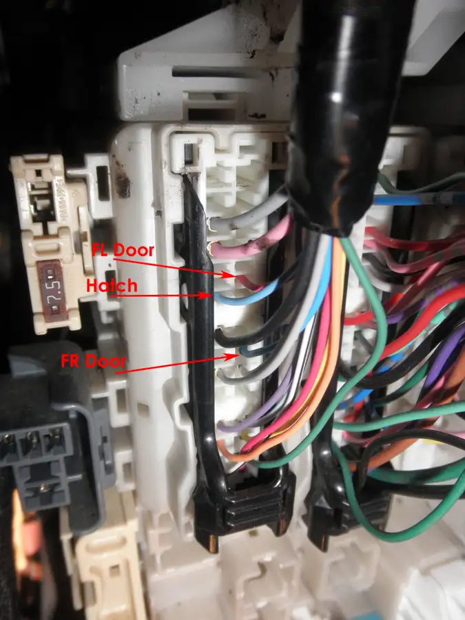
Attached picture not availableis there suppose to be any wire on the pin? cause there is none on the wire you mentioned? or just stick the wire from the alarm in the open harness that you mentioned?
CTScottThread starterUSA, CT · Nov 21, 2010#82 Originally Posted by
chexmix ↑ is there suppose to be any wire on the pin? cause there is none on the wire you mentioned? or just stick the wire from the alarm in the open harness that you mentioned?
There is no wire on any of the 5 pins listed above?
yup no wires
CTScottThread starterUSA, CT · Nov 22, 2010#84Here's a picture from Crashy, who is an 08 Liftback without power:
Originally Posted by yarismadness ↑
Very complete document! Thank you CTScott!
Now i can make some additions:
1- The parking brake switch (-) can be located in the Running Light Relay connector, light green cable, position 11.
2- For starters that have only one ignition output, I've chosen to connect my ignition output(+) to Ignition 2 (+ pink) , then link Ignition 2 to Ignition 1 with a 3Amps diode (white band towards Ignition 1 - green). I don't know if I could have link them together, but this worked. Attention: I didn't verify the current through the diode (as I should have), so I don't know if the 3Amps work for everybody on every condition.
3- I've find out a way connect a single start wire (+), and NOT NEED to override the clunch switch. Connect two diodes, one from your start wire (+), one diode to the starter wire (white band towards the starter - black wire ), and another from your start wire to the clunch connector (white band towards the connector - black wire )
the diodes I've used are the SB360 (schottky diodes, 60V 3Amps), almost any type of diode should do (OF THE RIGHT current!!!!!). If doubt, MEASURE IT!
They can be found at
www.digikey.com Good starting!!!
Nice additions.
The 3A diodes should be more than sufficient, as the ignition switch only switches power to a relay coil (~75mA) for starting.
i have a 08 yaris and im tryin to hook up a prostart remote starter, the car does have the key immobilezer and i have connected a idatalink by bass module , everything works fine except the car wont start with the remote, it will crank but not start?, i followed scotts diy which is awsome , on thing is that his diy shows a key sense wire where as my starter or immobileizer by pass ask for no such wire. ? woundering if some could please drop some input hear, i am an automoitve tech. and have connected everything as my instuctions say , ANYONE? LOL
CTScottThread starterUSA, CT · Dec 11, 2010#87 Originally Posted by
hatch2008 ↑ i have a 08 yaris and im tryin to hook up a prostart remote starter, the car does have the key immobilezer and i have connected a idatalink by bass module , everything works fine except the car wont start with the remote, it will crank but not start?, i followed scotts diy which is awsome , on thing is that his diy shows a key sense wire where as my starter or immobileizer by pass ask for no such wire. ? woundering if some could please drop some input hear, i am an automoitve tech. and have connected everything as my instuctions say , ANYONE? LOL
Which idatalink did you buy? Can you post a pic of the wiring diagram that came with it?
Also, the bypass modules typically have a learning mode, where they read your key, so they can emulate it. Did you go through that procedure?
ill try to upload the diagram tomorrow as it is midnight hear rite now , and yes i have learned the key, it wouldnt work at alll until the key was learned. almost seems like its missing a signal form the ign or immizer.
CTScottThread starterUSA, CT · Dec 11, 2010#89 Originally Posted by
hatch2008 ↑ ill try to upload the diagram tomorrow as it is midnight hear rite now , and yes i have learned the key, it wouldnt work at alll until the key was learned. almost seems like its missing a signal form the ign or immizer.
What's the model number of the one you bought? It looks like their install manuals are available on their website.
this is the by pass im useing and im using type 1 wire diagram.
OK - I assume your remote starter uses the DBI port?
Does the LED stay solid green when starting?
Yaris PAVEL94Michigan · Dec 11, 2010#92Does anybody know how the new apps for Viper remote starters work and how to set it up? Because I'm getting my new phone( BB Curve2)next week and I want to try it.THANKS
CTScottThread starterUSA, CT · Dec 12, 2010#93 Originally Posted by
Yaris PAVEL94 ↑ Does anybody know how the new apps for Viper remote starters work and how to set it up? Because I'm getting my new phone( BB Curve2)next week and I want to try it.THANKS
The ones with the cell phone interface install just like the keyfob ones. The only issue with them is that there is a monthly subscription fee for hanging it on the cell network.
ya mine is using the dbi port
hatch2008canada · Dec 12, 2010#95the led is doing the proper lighting when flashing , i spent like 7 hours on this yesterday and made sure all that ws good .
CTScottThread starterUSA, CT · Dec 12, 2010#96 Originally Posted by
hatch2008 ↑ ya mine is using the dbi port
OK - So that meant that you only had to wire it to the key transponder receiver.
Did the registration process go correctly (and is the module showing the green light)?
For your remote starter, what model is that?
If the remote starter didn't have a connection for key presence, the issue may be that the remote starter is telling the bypass module to send the key data at the wrong time.
its a prostart ct 3371 , and as far as i can tell there isnt a key sense connections jus the ign green, the white wire off the ign, the black starter wire. and the imm. hooks into the imm. connctor and obd connector .
hatch2008canada · Dec 12, 2010#98im reading through the prostart again and notice inthe programming of the prostart im mode 3 the default is xpresskit, but my bypass is connected to the ads port , so i will try changing that becuase if that is inncorect then the prostart is looking in the wrong place for the by pass, so i could very well be an idiot today lol .. make sense too you
hatch2008canada · Dec 12, 2010#99whats the differnece of the ign 1 wire and ign 2 wire on your diy
hatch2008canada · Dec 12, 2010#100from what google has told me i need to have ign 1 and 2 connected to a relay which as far as i can tell my prostart instructions say is optinal, also when the car is cranking if i put the key in and to the on pos. it starts. anyone noe what i should do hear , or how the2 ign wires are suppose to be connected. starting to really hate prostart lol.
 Yarisworld