Yarisworld Archive

DIY - Bypassing Tire Pressure Warning System (TPWS / TPMS)

217 posts · 385,870 views · page 1 of 5

CTScottOriginal postUSA, CT · Nov 24, 2008#1
Note: Please jump to page 3, post #45. The first pass of a solution on pages 1-3 ended up not working.

For the simple method, please jump to post 115. This method does not require resistors.

DIY - Bypassing Tire Pressure Warning System (TPWS / TPMS)


Following is a DIY to disable the system, without causing the TPWS light or MIL (malfunction indicator light {or check engine light, as some like to call it}) to light.

A while back there was a thread about the issues with either using rims which are not compatible with the tire pressure sensors or running two sets of rims. The Yaris TPWS can only be programmed to respond to one set of four sensors. To switch to a second set, you would have to bring your car to the dealer to have the TPWS reprogrammed for the second set (This is typically about a $90 charge).

I did a bit of reverse engineering on the TPWS and believed that I found a soultion. Linny recently tried this solution and verified that after more than 100 miles of driving there were no issues.


Procedure :
(WARNING: Modifying anything on the Yaris is done at your own risk!!!)


The TPMS ECU is located behind the lower passenger glove box:
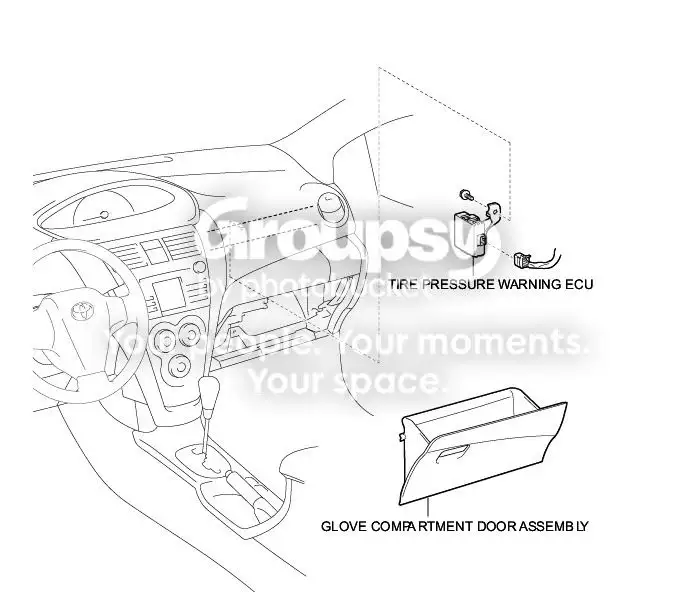


The TPWS system will only report an issue with not hearing from the sensors if for 15 minutes it doesn't hear from a sensor while the vehicle speed is 5 MPH or greater and the Engine speed is 1000 RPM or more.

To keep the system from reporting an error, do the following:

1. Start without an error: If you start with the system in the error free state (by starting the vehicle and having the 4 tires with the sensors next to the vehicle (or mounted on it) and ensure that the TPWS light is not lit or flashing.

2. Shut the engine off.

3. Pull out the lower passenger glove box and locate the TPWS ECU (to the right, just above the fan assembly):
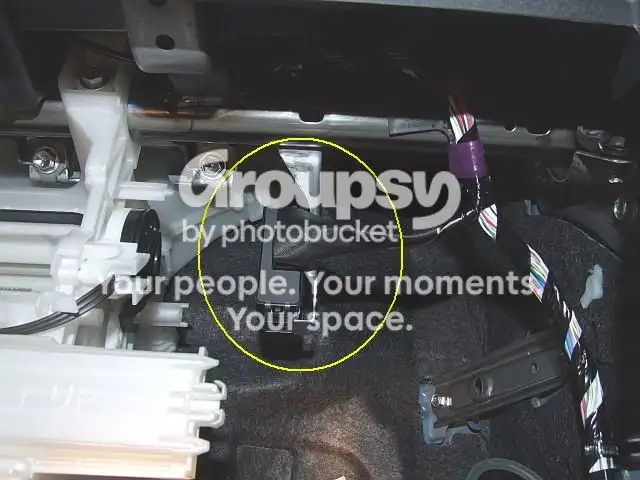


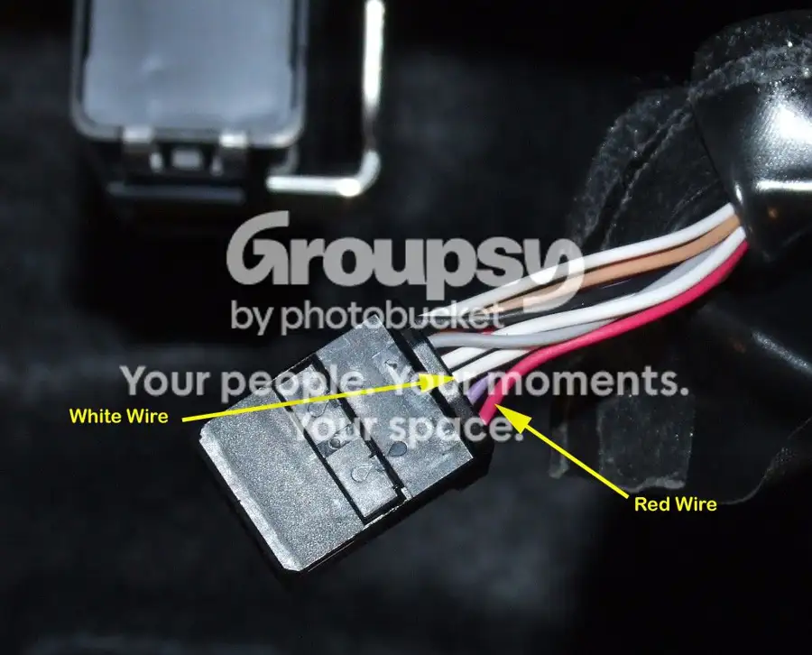
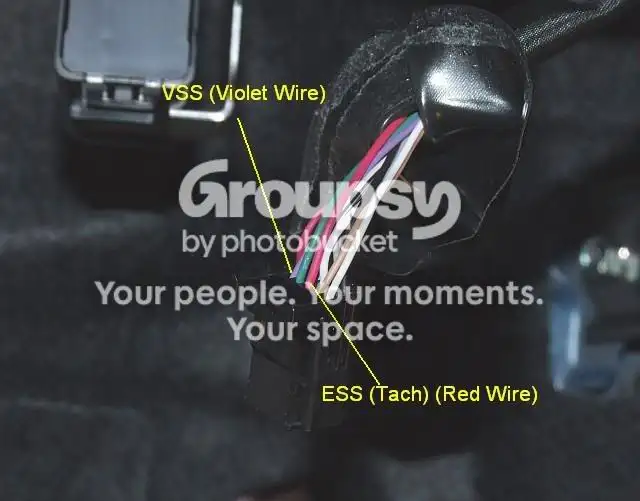
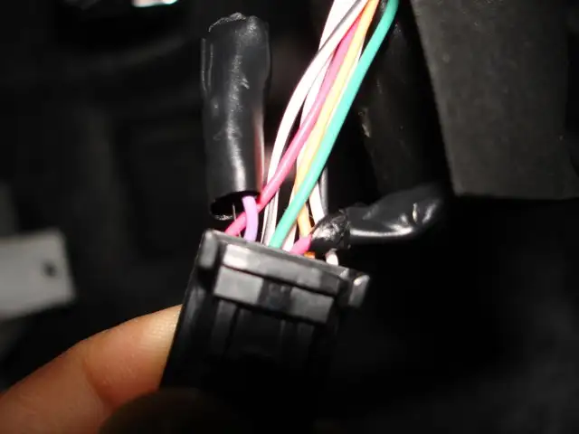
3. Clip and cap both ends of the VSS and ESS wires to the TPWS ECU. Leave a couple of inches on the connector side so that you can resplice if you wish to re-enable the system. The connector is shown below. The VSS wire is the Violet one and the ESS wire is the red one, two pins after the violet one. Also, if you wish to switch between a set of rims with sensors and a set without, you can add a DPST (dual pole, single throw) switch to disconnect / reconnect both wires as desired to disable/enable the TPWS.


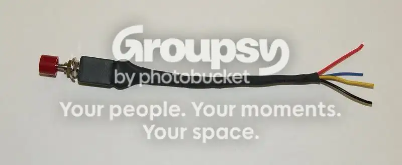
For adding the switch the following is a good choice:
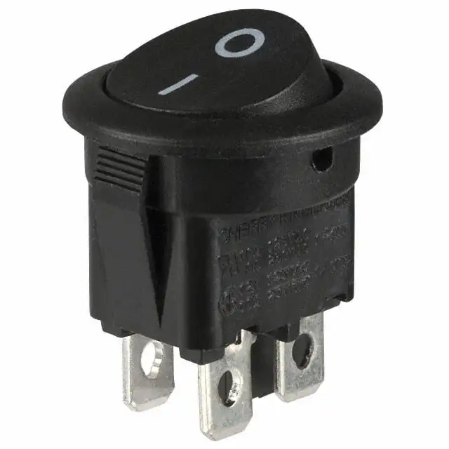


http://search.digikey.com/scripts/Dk...?name=CH867-ND

To wire the switch, connect the cut wires to the sets of terminals on either side of the switch as follows:

Red - - Red
Vio - - Vio


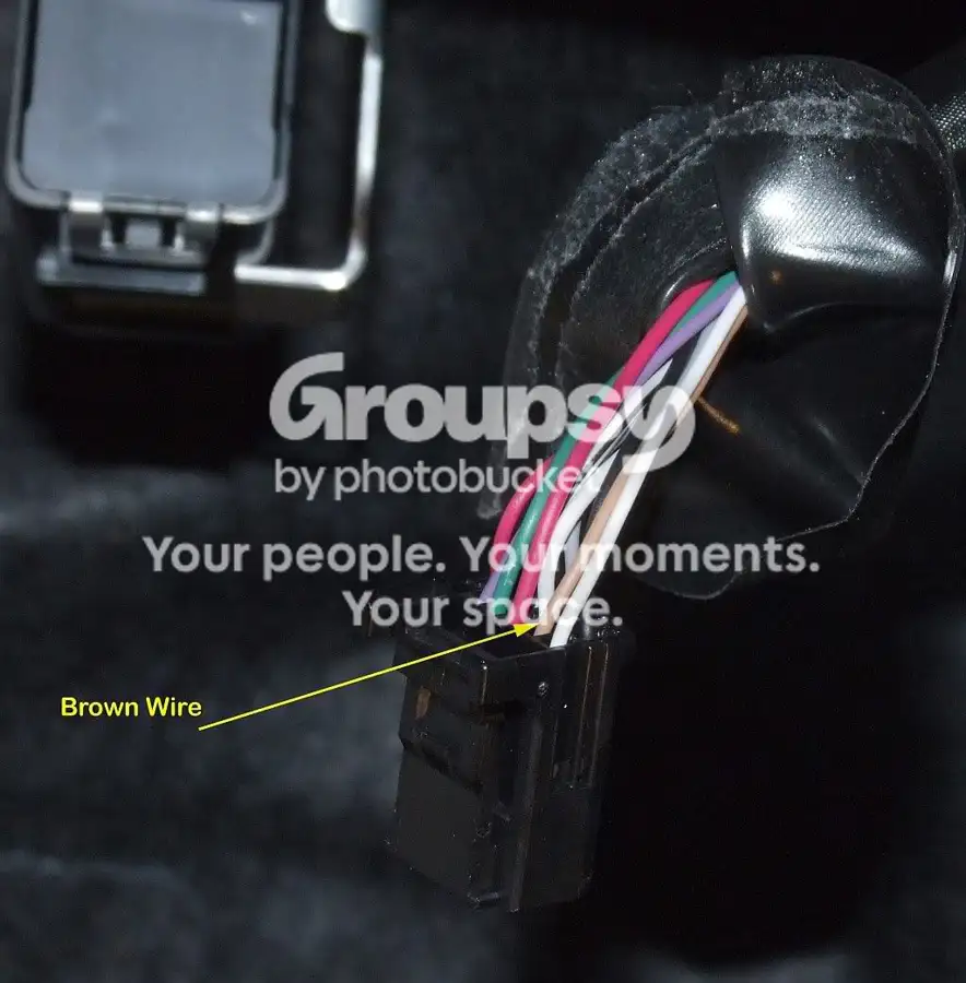
Someone posted a DIY of disabling the feed to the light (the brown wire on the connector above, if you were wondering). The problem with just clipping this wire is that the DTCs will still be logged and may result in your Malfunction Indicator Light coming on.
Replies 216

TamagoOff Grid · Nov 24, 2008#2
very nice :)
kounj · Nov 24, 2008#3
i will be doing this in the spring.thank you.👏
TheSilkySmoothNew Hampshire · Nov 25, 2008#4
Super DIY write up. Thank you CTS for the effort! I am planning to put vinter tyres on My Daughter's Yaris and was concerned about setting a code as she is due for Emissions and saftey inspection this november. The SW seem like a good idea. CTS You dont have to shunt any of the cut wires to keep an open antenna out of the ECU?

Does anyone know if the 14" steel rims sold through Tire rack or Discount Tire Direct will clear the calipers? Her car has optional 15 inch rims. I wish to put a 165-70 snows on the front to get better force/unit area (µN/cm2) at the contact patch.

Thank you for helping,

- Papa
TamagoOff Grid · Nov 25, 2008#5
Originally Posted by TheSilkySmooth ↑
Super DIY write up. Thank you CTS for the effort! I am planning to put vinter tyres on My Daughter's Yaris and was concerned about setting a code as she is due for Emissions and saftey inspection this november. The SW seem like a good idea. CTS You dont have to shunt any of the cut wires to keep an open antenna out of the ECU?

Does anyone know if the 14" steel rims sold through Tire rack or Discount Tire Direct will clear the calipers? Her car has optional 15 inch rims. I wish to put a 165-70 snows on the front to get better force/unit area (µN/cm2) at the contact patch.

Thank you for helping,

- Papa
14's should clear fine, stock brakes aren't huge.. +39 offset should work as well
CTScottThread starterUSA, CT · Nov 25, 2008#6
Originally Posted by TheSilkySmooth ↑
Super DIY write up. Thank you CTS for the effort! I am planning to put vinter tyres on My Daughter's Yaris and was concerned about setting a code as she is due for Emissions and saftey inspection this november. The SW seem like a good idea. CTS You dont have to shunt any of the cut wires to keep an open antenna out of the ECU?

Does anyone know if the 14" steel rims sold through Tire rack or Discount Tire Direct will clear the calipers? Her car has optional 15 inch rims. I wish to put a 165-70 snows on the front to get better force/unit area (µN/cm2) at the contact patch.

Thank you for helping,

- Papa

No shunting is required. The two wires we are disconnecting are both 12 V analog signals which the ECU is pulling through A to D converters. We shouldn't be able to pick up enough noise to cause a false signal detection.
TamagoOff Grid · Nov 25, 2008#7
Originally Posted by CTScott ↑
No shunting is required. The two wires we are disconnecting are both 12 V analog signals which the ECU is pulling through A to D converters. We shouldn't be able to pick up enough noise to cause a false signal detection.
i thought speed and tach signals were both pulse signals.... ?
CTScottThread starterUSA, CT · Nov 25, 2008#8
Originally Posted by Tamago ↑
i thought speed and tach signals were both pulse signals.... ?
They are frequency modulated pulses. The TPMS microcontroller pulls them in through an analog input.
TamagoOff Grid · Nov 25, 2008#9
Originally Posted by CTScott ↑
They are frequency modulated pulses. The TPMS microcontroller pulls them in through an analog input.
ah cool so where they enter the ENGINE ecu they're pulse signals, then they go out to the cluster as pulses (correct me if i'm wrong, i recollect setting up a Defi VSD heads up display, and grabbed pulse signals for tach/speed) and the ECU also sends analog outputs to the TPMS?

do you have a wiring diagram of the ECU?
CTScottThread starterUSA, CT · Nov 25, 2008#10
Originally Posted by Tamago ↑
ah cool so where they enter the ENGINE ecu they're pulse signals, then they go out to the cluster as pulses (correct me if i'm wrong, i recollect setting up a Defi VSD heads up display, and grabbed pulse signals for tach/speed) and the ECU also sends analog outputs to the TPMS?

do you have a wiring diagram of the ECU?
The ECU sends the same pulsed signal to the cluster and the TPWS. The Combo Meter has a microcontroller, which reads the tach and VSS inputs directly, as well as a CAN bus interface to get the odo data and MIL input from the ECU. All of the "data" signals are 12 V, so the microcontrollers have to level shift them to use them (via optoisolator, A-D, etc.).

The Defi's micro would have to do the same thing. By the way, was the Defi VSD worth the money?

For the wiring diagrams, I just have the 09 service manual.
TamagoOff Grid · Nov 25, 2008#11
Originally Posted by CTScott ↑
The ECU sends the same pulsed signal to the cluster and the TPWS. The Combo Meter has a microcontroller, which reads the tach and VSS inputs directly, as well as a CAN bus interface to get the odo data and MIL input from the ECU. All of the "data" signals are 12 V, so the microcontrollers have to level shift them to use them (via optoisolator, A-D, etc.).

The Defi's micro would have to do the same thing. By the way, was the Defi VSD worth the money?

For the wiring diagrams, I just have the 09 service manual.
i've installed 3 sets.. one on my xA the base VSD.. it was essential to life for me until it was vandalized :( it would record max speed/RPM which worked well for primitive datalogging at autocross..

the second one was the VSD that would hook up to the LINK system.. this one went in the yaris. speed/tach on the windshield is awesome..

i now have a VSD-X for my xA.. it has its own screen. i had it installed for a bit then removed it. it's a nice piece but a little OTT for this build. i believe DEFI has discontinued all their HUD's..
ChupacabraCT · Nov 25, 2008#12
Scott,
Insanely awesome thread! Thank you!!!....
blacksandiegovitzJust chillin' out brah ! · Nov 25, 2008#13
Man soooo killer. Installed trd/racing hart 18" and didn't have the sensors installed on them , Im so over the "warning" light on the dash . I'll be doing this this weekend .
linnyMn · Nov 26, 2008#14
The hardest part about this procedure was pulling the glove box out! Thanks CTSCOTT! I tried to get the service guy at our dealer to tell me how to disable the system and he wouldn't budge. He would just offer that what most people do is simply 'deal' with the light since most do not have the want or resources to drop $90 each time they want to switch rims/tires.
mikenacaratoBrentwood, TN · Nov 26, 2008#15
very nice! i was just about to ask if there was a way to bypass it and then i saw this.
RatboyBaltimore · Nov 26, 2008#16
okay...you guys lost me. Do you need to cut the wires or can you just leave it unplugged? Or are you just cutting the two wires?
linnyMn · Nov 26, 2008#17
I cut the two wires as specified in the pictures provided by CTSCOTT. After cutting the wires I wrapped each of the ends from the two wires in electrical tape. I then plugged the connector back into the ECU unit and that is it!!
YariceVictorville, CA · Nov 26, 2008#18
Does this project also work for an 2008 3dr LB?
CTScottThread starterUSA, CT · Nov 26, 2008#19
Originally Posted by Yarice ↑
Does this project also work for an 2008 3dr LB?
Yes. TPWS is identical on 2008 and 2009 3 and 5 door LBs and Sedans as well.
CTScottThread starterUSA, CT · Nov 26, 2008#20
Originally Posted by Ratboy ↑
okay...you guys lost me. Do you need to cut the wires or can you just leave it unplugged? Or are you just cutting the two wires?
You do need to keep the connector plugged in (with those two wires cut) to sucessfully do the mod. If you just unplug the connector, the TPWS light will immediately come on and will stay on until it is plugged back in.

Cutting those two wires fools the Tire Pressure Warning System into thinking that the car is not moving and the engine is not running. The TPWS will not report an error if it doesn't hear from the tire sensors as long as the car is not rolling and the engine is not running.
TheSilkySmoothNew Hampshire · Nov 27, 2008#21
My daughters car seem to idle low and loose pick-up and have flat spot on throttle tip-in when the heater or headlights or radio are on. Is there a power buss or GND I can check that may be intermittent? Also does the Cluster dimmer use PWM PSU for voltage control for brightnes or is it just a ballast pot (I'm thinking NO here in digital age). Reason I ask is, I was driving here car and someone knocked-off the display brightness, I turned the knob to mid range and I lost power and engine got buzzy on the highway. May just co-incidence. I wondering if this car is hyper-sensitive to noise on the power buss - also given SS regulated DC which is pretty noisy too - enough to false certain sensor input? I suppose what I am getting at when you drive car initial reaction is - this car has electrical problem - it s over sensitive to control settings. Everything off it runs OK again after ~ 1 cold and a couple HOT key-on/key-offs. This is bad enough I consider SELLING it since it appears on the unrepairable given the tech training level we have around here (NH). Possibly anything I should look for on the hand held - like fuel trim or low E at ECU buss? I want to look for a pattern of corrupted look up tables (and I dont have OBDii scanner, but plan to purchace one.)

Thank you
YariceVictorville, CA · Nov 27, 2008#22
Nice, thanx for that info, cant wait to try it out.
TamagoOff Grid · Nov 27, 2008#23
Originally Posted by TheSilkySmooth ↑
My daughters car seem to idle low and loose pick-up and have flat spot on throttle tip-in when the heater or headlights or radio are on. Is there a power buss or GND I can check that may be intermittent? Also does the Cluster dimmer use PWM PSU for voltage control for brightnes or is it just a ballast pot (I'm thinking NO here in digital age). Reason I ask is, I was driving here car and someone knocked-off the display brightness, I turned the knob to mid range and I lost power and engine got buzzy on the highway. May just co-incidence. I wondering if this car is hyper-sensitive to noise on the power buss - also given SS regulated DC which is pretty noisy too - enough to false certain sensor input? I suppose what I am getting at when you drive car initial reaction is - this car has electrical problem - it s over sensitive to control settings. Everything off it runs OK again after ~ 1 cold and a couple HOT key-on/key-offs. This is bad enough I consider SELLING it since it appears on the unrepairable given the tech training level we have around here (NH). Possibly anything I should look for on the hand held - like fuel trim or low E at ECU buss? I want to look for a pattern of corrupted look up tables (and I dont have OBDii scanner, but plan to purchace one.)

Thank you
i think this question deserves its own thread ;)
YariceVictorville, CA · Nov 27, 2008#24
Just finished my lil project, no more stupid TPMS light, AHHH YEAHHH!!
ivanmadelineNC · Nov 28, 2008#25
I tried this today on my car but the light came back on did any one have this problem after cutting the cables. Thanks
CTScottThread starterUSA, CT · Nov 28, 2008#26
Originally Posted by ivanmadeline ↑
I tried this today on my car but the light came back on did any one have this problem after cutting the cables. Thanks
Was the light on before you clipped the wires? The system needs to start in a non-error state (i.e. light not on).
ivanmadelineNC · Nov 28, 2008#27
The light was off. I took the car to the dealer for the first oil change and i change the rimms before i went i told the to chech the light that it was on an they reset it for me. I got a question I can remeber is it suppose to come on when you first start the car and it goes off again. Tha's what it was doing after they reset on the dealer but the light was off when i cut the wires. thanks for your response.
YariceVictorville, CA · Nov 28, 2008#28
Mines didnt work either, my light came on after 15 miles or 15 minutes of driving. Started the car with no TMPS indicator light, shut the car off and cut the 2 wires and cap them and re-plugged the harness. Tired doing this twice, the second time I made sure the TMPS indicator lights wernt present and I disconnect and reconnected the lights came on after 15 miles.
YariceVictorville, CA · Nov 28, 2008#29
this is what I did
DSC01063_640x480.shkl.jpgDSC01068_640x480.shkl.jpg
CTScottThread starterUSA, CT · Nov 28, 2008#30
The system has to be in comm with the sensors when you do the mod (step 1). You need to have the sensors on your old rims (with tires) and have them next to the car before you shut it off and cut the wires.
YariceVictorville, CA · Nov 28, 2008#31
Thats what I did, all 4 tires w/TMPS sensor were next to my new rims, then I started the car, no TMPS lights, then I shut off the car, then I cut and cap the wires, it was groovy for about 15 minutes.
ivanmadelineNC · Nov 28, 2008#32
I had the factory rims with the sensors when I did all the steps. After I finished and saw the that the light was off I change the rims.
YariceVictorville, CA · Nov 28, 2008#33
So your telling me I have to mount the stock wheels w/TMPS on first and then do all the the steps and them mount my new rims?
ivanmadelineNC · Nov 28, 2008#34
Originally Posted by Yarice ↑
So your telling me I have to mount the stock wheels w/TMPS on first and then do all the the steps and them mount my new rims?
No I was letting CTScott know that i had the sensors on when I did all the steps and that It didn't work.
CTScottThread starterUSA, CT · Nov 28, 2008#35
OK. Now we have to figure out what is different between the two of yours', and Linny's...
ivanmadelineNC · Nov 28, 2008#36
Mine is and 08 Sedan stick just in case.
YariceVictorville, CA · Nov 28, 2008#37
Mines an 2008 3dr LB
YariceVictorville, CA · Nov 28, 2008#38
Ive done this 3 times and im not gonna move the car till tomorrow and let the car sit overnight if thats gonna make a difference, if not im gonna put everything back the way it was.
CTScottThread starterUSA, CT · Nov 29, 2008#39
OK. Linny just PM'd me. His had been working fine until he headed out of town for Thanksgiving. All of his trips prior had been short (<6 miles). About 15 minutes into his trip the light came on.

So, it looks like this solution does not work - It looks like the third component is time.
CTScottThread starterUSA, CT · Nov 29, 2008#40
Originally Posted by CTScott ↑
OK. Linny just PM'd me. His had been working fine until he headed out of town for Thanksgiving. All of his trips prior had been short (<6 miles). About 15 minutes into his trip the light came on.

So, it looks like this solution does not work - It looks like the third component is time.
Looked into it a bit more. The TPMS starts a timer once it receives power. After ~15 minutes of power and no comm from the sensors it turns the light on.

I am now experimenting with just using the brown wire, which is the output to the combination meter. To turn the light off, the TPWS module supplies ~4.0V to the brown wire. At 2.4V or less the light will come on.

I disconnected the TPWS and applied ~4.0 V to the brown wire (via a resistor voltage divider from the 12V supply on the connector). The light does not light. I will drive around for a week or so to make sure that eliminating the module doesn't cause a DTC to be thrown.
ivanmadelineNC · Nov 29, 2008#41
Thanks for the help.
CTScottThread starterUSA, CT · Nov 29, 2008#42
Originally Posted by CTScott ↑
Looked into it a bit more. The TPMS starts a timer once it receives power. After ~15 minutes of power and no comm from the sensors it turns the light on.

I am now experimenting with just using the brown wire, which is the output to the combination meter. To turn the light off, the TPWS module supplies ~4.0V to the brown wire. At 2.4V or less the light will come on.

I disconnected the TPWS and applied ~4.0 V to the brown wire (via a resistor voltage divider from the 12V supply on the connector). The light does not light. I will drive around for a week or so to make sure that eliminating the module doesn't cause a DTC to be thrown.

OK. I've been driving around today with the TPWS disconnected as above, and no TPWS light. We are going out to dinner tonight, and where we are going is about 35 minutes away, so that will be a good test. If the light remains off and I still don't have any DTCs logged, when I get home tonight I'll post the updated method.
YariceVictorville, CA · Nov 29, 2008#43
Sweet, thanxs for the update, were all waiting to see how it goes.
blacksandiegovitzJust chillin' out brah ! · Nov 29, 2008#44
damn , so this doesn't work ???? good thing I didnt go cutting wires . Im just gonna have my sensors installed on my racingharts when I get them powder coated .
CTScottThread starterUSA, CT · Nov 30, 2008#45
Originally Posted by CTScott ↑
OK. I've been driving around today with the TPWS disconnected as above, and no TPWS light. We are going out to dinner tonight, and where we are going is about 35 minutes away, so that will be a good test. If the light remains off and I still don't have any DTCs logged, when I get home tonight I'll post the updated method.
OK. The new solution looks good. After a bunch of short trips and a 30 minute each way dinner run, no TPWS light and no logged DTCs. The new solution goes as follows (and does not require the system to have been light-free prior):

This procedure requires some minor soldering and can be done with or without a switch to re-enable the TPWS.

1. Make a simple voltage divider to provide ~4 Volts to the TPWS light input to the Combination meter.


Parts Required:
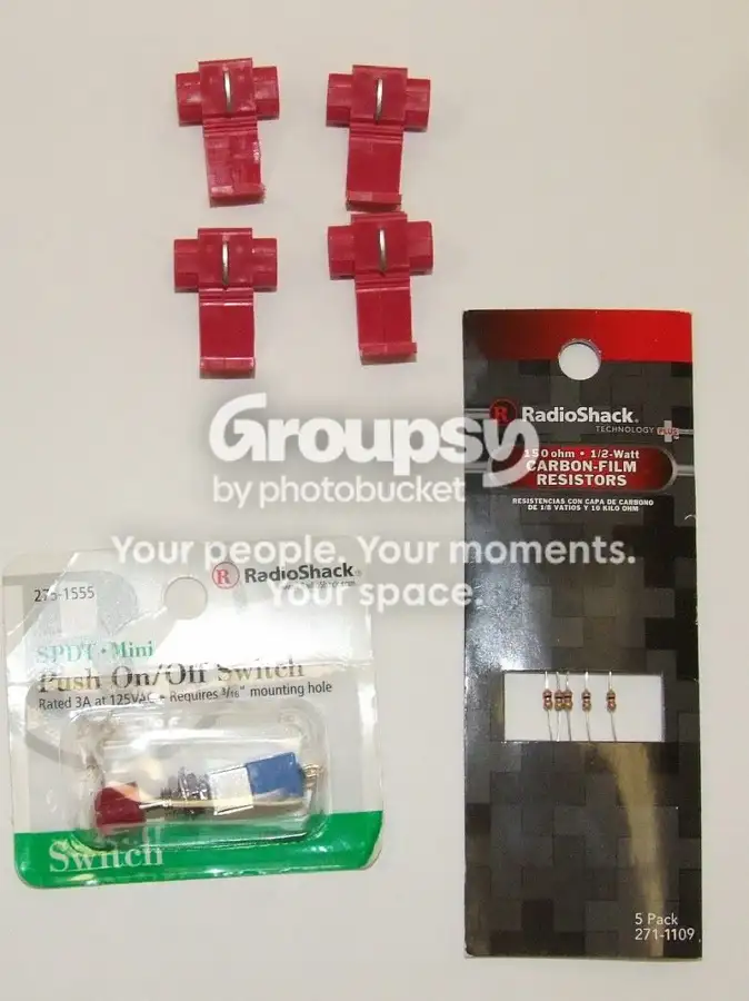
3 150 ohm resistors (radio shack part # 271-1109 for a 5 pack)
22 AWG Wire (Red, Black, green (also yellow and blue if using switch)
Switch(optional), SPDT toggle or push on/off (Radio Shack part # 275-1555)
Heat shrink tubing or electrical tape
18-22 AWG (red) tap-splice connectors (3 for no switch, 4 for switch)

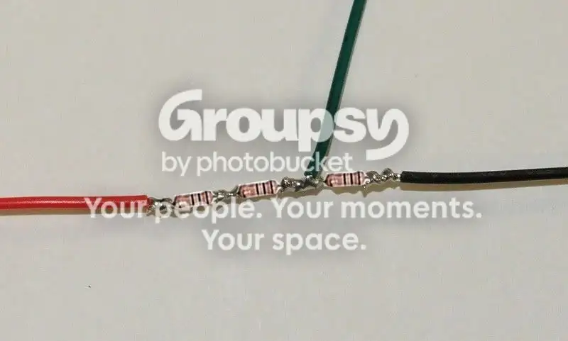
a. Solder three 150 ohm resistors end to end.
b. Solder a 6" piece of black wire to one end and a 6" piece of red wire to the opposite end of the string of resistors.
c. Solder a 6" piece of green wire between the first and second resistor from the black wire end.


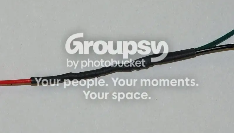
d. Cover the resistors with heat shrink tubing or electrical tape.


e. Skip to step 2 if not adding a switch.
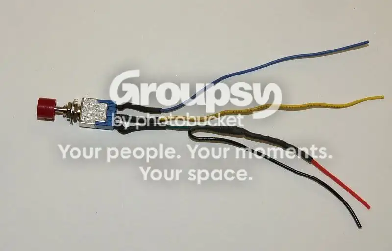
f. Solder a 6" piece yellow wire to the center terminal of the switch
g. Solder a 6" piece of blue wire to one of the end terminals of the switch.
h. Solder the free end of the green wire to the other end terminal of the switch.


i. Cover the exposed switch terminals with heat shrink tubing or electrical tape.


2. With the car powered off, unplug the TPWS module connector
3. Clip the brown wire (leave a couple of inches so you can reconnect later if so desired)


4. Using a tap splice, connect the red wire to the red wire on pin 7 (This red is next to an empty spot at position 8 {RED, empty, white, white, grey, black})
5. Using a tap splice, connect the black wire to white wire on pin 9 (Next to the empty spot after the red wire {red, empty, WHITE, white, grey, black})


6. If not using a switch, connect the green wire to the brown wire which goes to the combination meter (not the connector end of the cut wire).
7. If using the switch, connect the blue wire to the brown wire which goes to the combination meter (not the connector end of the cut wire).
8. If using the switch, connect the yellow wire to the other end of the brown wire, which is attached to the connector.
9. If not using the switch, leave the TPWS connector off. If using the switch, plug the connector into the TPWS.
10. Turn on the ignition. If not using the switch, the TPWS light should be off.
11. If using the switch and the TPWS light is on, press the switch and the light should turn off.
eTiMaGoBangkok, Thailand · Nov 30, 2008#46
interesting... One thing I am curious about, what kind of signal do the sensors give out? Is it just a binary "too low/good" signal or an actual value representing the pressure for each wheel? If it's the second case, it would be quite cool to hack those signals into an actual per-wheel pressure display!
CTScottThread starterUSA, CT · Nov 30, 2008#47
Originally Posted by eTiMaGo ↑
interesting... One thing I am curious about, what kind of signal do the sensors give out? Is it just a binary "too low/good" signal or an actual value representing the pressure for each wheel? If it's the second case, it would be quite cool to hack those signals into an actual per-wheel pressure display!
The sensors transmit a packet with their ID, pressure, and temperature. Hacking the protocol would be an interesting project...
linnyMn · Nov 30, 2008#48
Thank you for putting so much effort into this modification CTSCOTT. I will make a trip to Radio Shack when they open this morning!🙂
CTScottThread starterUSA, CT · Nov 30, 2008#49
Originally Posted by linny ↑
Thank you for putting so much effort into this modification CTSCOTT. I will make a trip to Radio Shack when they open this morning!🙂
I realize that this solution is a bit more work than the original cut two wires one, so if anyone needs to do this and doesn't have the equipment, etc. to solder it up, I can make it up and ship it as a nice little kit.
ivanmadelineNC · Nov 30, 2008#50
Thanks for all the work CTSCOTT I just got back from Radio Shack with all the items. I hope that this time it all works.