 Yarisworld
looks like I'm buying an 09 service manual there is no such fuse in that locationOriginally Posted by CTScott ↑In the fuse panel that faces the driver's side floor mat at the bottom left of the dash.
DIY - Bypassing Tire Pressure Warning System (TPWS / TPMS)
217 posts · 385,870 views · page 3 of 5
Replies continued
Originally Posted by regal ↑looks like I'm buying an 09 service manual there is no such fuse in that location
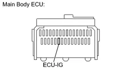
nothing there but I butch of relays, no fuses
are these odd ball fuses or something?
You're looking in the wrong place. Lay on the floor and look up at the bottom of the dash (directly under where you are looking). You'll see a plastic panel with the fuse locations. Pull that plastic cover off and the fuses will be visible.Originally Posted by regal ↑are these odd ball fuses or something?
found it thanks a bunch
but now when I turn my headlights on the instrument panel goes dim, under daytime running lights the dash is illuminated, very odd and can't find anything in the owners manual.
That's the normal behavior for the instrument panel lighting - Full bright with headlights off and dimmed, per the knob, with headlights on.Originally Posted by regal ↑but now when I turn my headlights on the instrument panel goes dim, under daytime running lights the dash is illuminated, very odd and can't find anything in the owners manual.
I'll figure out this Toyota eventually. Thanks again.Originally Posted by CTScott ↑That's the normal behavior for the instrument panel lighting - Full bright with headlights off and dimmed, per the knob, with headlights on.
I finally got it to work after cutting about half the waires off, I am using a different 12V source and the voltage divider, the TPMS unit is unplugged. Not pretty but does work. CTScottt mentioned there is a regulated 4V signal coming out of theTPMS uit, I couldn't find one on my 09 only a 6V.
Your Yaris has daytime running lights?Originally Posted by regal ↑but now when I turn my headlights on the instrument panel goes dim, under daytime running lights the dash is illuminated, very odd and can't find anything in the owners manual.
yes 09, found it was just the dimmer switch turned off, for some reason the dimmer switch dims the dash only when the headlihts are on.Originally Posted by Yaris Hilton ↑Your Yaris has daytime running lights?
My '07 & 2 '09s have normal headlights that you have to turn on, no DRLs. (Thankfully!) Must be a state law thing.
Sedans don't get the DRL options like the lifback. My old '07 had them as well as my new '09.
I did the switch today. I had to leave it dangleing because I don't think the quick connects (splicers) made a solid cut through the facotry wires. I'll get to it eventually lol.
I did the switch today. I had to leave it dangleing because I don't think the quick connects (splicers) made a solid cut through the facotry wires. I'll get to it eventually lol.
Originally Posted by Treyz ↑Sedans don't get the DRL options like the lifback. My old '07 had them as well as my new '09.
I did the switch today. I had to leave it dangleing because I don't think the quick connects (splicers) made a solid cut through the facotry wires. I'll get to it eventually lol.
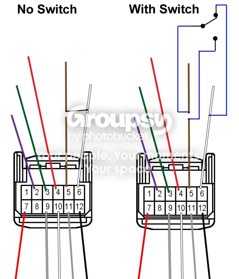
Here's an even easier method that I figured out one day. I just haven't gotten around to writing up a DIY on it:
So now we are back to three wires? I did the heat shrink and all with the 150ohms.
It's not cutting the VSS and ESS wires (like the original started with). In doing some reverse engineering of the TPWS, I realized that it has a regulated 5VDC output that powers the radio receiver module. Tapping the white wire in pin 5 gives us this regulated voltage, so the resistor voltage divider isn't necessary. Both methods work, but this one is a bit more simple.Originally Posted by Treyz ↑So now we are back to three wires? I did the heat shrink and all with the 150ohms.
I just took off my rims, I will be doing this in a little to get the light off permanently.
I found my 09 to have completely different colors, I used a DMM to find the right wires.
I re read this thread and realize I am not even close to competent to do this lol.
learn how to use a DMM they cost like $6 at harbor freight, use the resistors to split a 12V line to 5V and send to the indicator light.
Just look at post #115 above. As long as your wire colors/positions match up, it is quite simple, especially if you do the non-switch version. Basically, you clip one wire and tap it to another.Originally Posted by Keith Tinari ↑I re read this thread and realize I am not even close to competent to do this lol.
ehh I did the resistor thing anyway, so basically the resistors was just for a 5v dc?
Doesn't matter soldering is fun 👍 Anyways you da man CT
Doesn't matter soldering is fun 👍 Anyways you da man CT
i just completed this in 90 seconds with a pocket knife.
it'll take another 30 seconds when i have a piece of tape to finish.
it'll take another 30 seconds when i have a piece of tape to finish.
CT Scott:
Great thread. Using your scematic, I did the fix in 30 mintues.
Thanks!
Great thread. Using your scematic, I did the fix in 30 mintues.
Thanks!
Hmm I bought a rim for my Yaris with a useable tire but no sender. What happens if the warning light goes off! Ok to put tape over it?
The light will come on eventually. It doesn't affect anything other than being annoying. You can tape it, or do the mod.Originally Posted by bronsin ↑Hmm I bought a rim for my Yaris with a useable tire but no sender. What happens if the warning light goes off! Ok to put tape over it?
Now that I read it and understand it, the mod looks good!
Make sure you look at post 115. It was my 3rd iteration of the mod, and the simplest.Originally Posted by bronsin ↑Now that I read it and understand it, the mod looks good!
Yes I read the whole thing through a few times. (and I may read it some more!) Im used to buying $300 cars and fixing them (well...$300 cars 20 years ago) but this ECM stuff I have no clue. Thanks for figureing this out !
Thank you for the simple TPMS mod, CTScott!
Hi CT, I had my sensors moved to my aftermarket rims for non snow months. My factory steel rims have the snows with no sensors. In Summer no prob, but in winter the TPWL will start flashing for less than a minute then shut off until I restart the car. Sometimes it will come on and sometimes it wont but it always goes out after flashing. Is this typical?
Oops I said TPWL (tire pressure warning light) when I meant TPMS.
That's normal. If you store your summer tires somewhat near where you park the car, it will communicate with the sensors and be happy for a while. Once it is away from the tires for a bit, it will realize that it hasn't talked to the sensors and will turn the light on.Originally Posted by birdman ↑Hi CT, I had my sensors moved to my aftermarket rims for non snow months. My factory steel rims have the snows with no sensors. In Summer no prob, but in winter the TPWL will start flashing for less than a minute then shut off until I restart the car. Sometimes it will come on and sometimes it wont but it always goes out after flashing. Is this typical?
Even when I go on long winter trips for several days the light will often start flashing for less than a minute and always go out. Normal too?
There are so many really smart people here clearing every hurdle placed before them that I am awe struck by it. I am very fortunate to have stumbled into this awesome community.
I've bought a lot of "stuff" I intended to add/mod to my Yaris, this was the first mod I did. To me it is mandatory. The TPMS is a sales gimmick, nothing more. The batteries in the sensors will eventially go bad, you must have have the ability to swap rims without an idiot light.
Here is another way to implement CTScott's mod to make the TPMS light stay off no matter what. It's electrically identical, quick, easy and leaves no readily observable evidence of "tampering". It's also a reversible mod. You'll need a small side-cutter, a soldering iron and about 10 minutes of time.
The three pictures should say it all.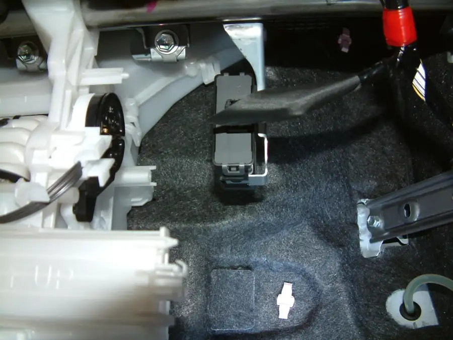
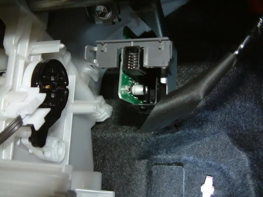
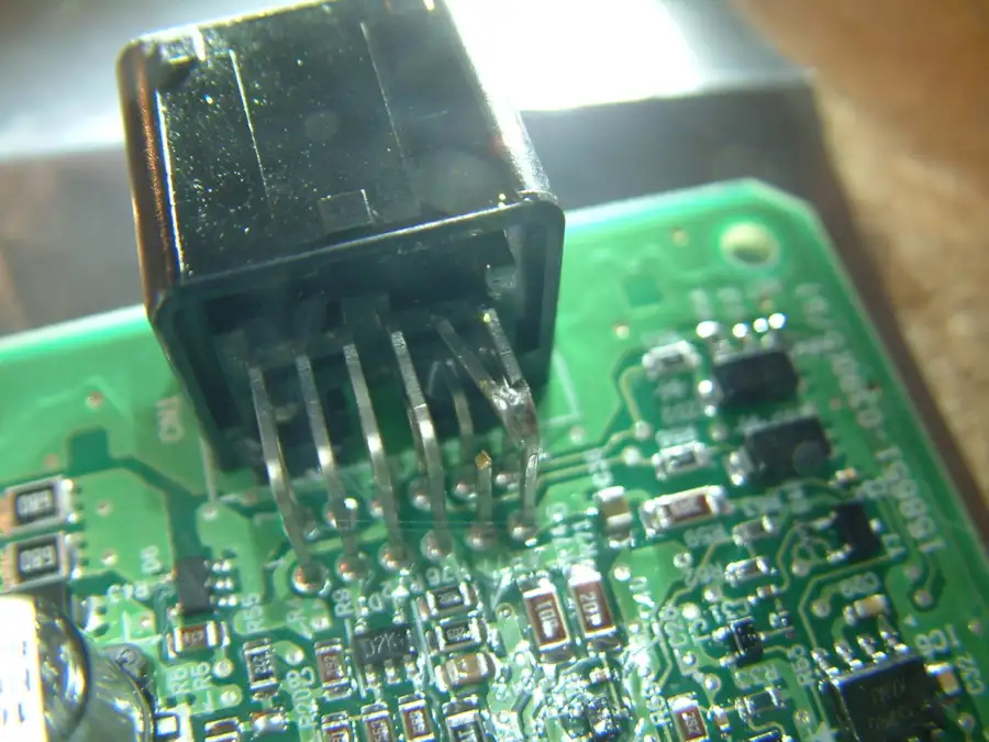
The three pictures should say it all.
^Nice!
Totally out of view for those worried about it being seen when they go in for warranty work.
Totally out of view for those worried about it being seen when they go in for warranty work.
I gotta do this .. mine still doesn't work right and this is with the resistors. Not working for some reason, but Domo blocks the view of it so it's not really annoying.
Thanks to them, I was able to make mine with a switch.
Picture lost · i279.photobucket.com
Picture lost · i279.photobucket.com
Picture lost · i279.photobucket.com
Picture lost · i279.photobucket.com
👍I did the latest tpms light disable as per post by yarisugi. I got a small DPDT from Radio Shack. Good thing I had a tiny pair of side cutters. I can flip the switch back and forth with the correct results every time. I did this and then put on some 14 x 6 BBS wheels on with 185/60-14 wheels and tires. The car handles much better than with the 15" steelies. I can chirp the tires now at will. It likes the smaller tires and lower gearing. Ya the speedo is off now, but I get 15k a year on my lease. Thanks to all from this post for the awesome, accurate work and reporting. I'll try and post a photo of the car soon.
doc
doc
I'm finally ready to do this fix. The switch option requires that the snipped brown wire that is attached to the connector be grounded, while the upper part is wired to the switch. Right?
No, there is not a ground connection. With the switch, you are either leaving the brown wire connected or connecting it to the +5V line.Originally Posted by birdman ↑I'm finally ready to do this fix. The switch option requires that the snipped brown wire that is attached to the connector be grounded, while the upper part is wired to the switch. Right?
In post #115 the diagram shows the brown wire is cut. The upper part you have pictured connected to a blue line going to one side of the switch. On the other side of the switch there is a blue line that splices to a white wire. The portion of the brown wire that is attached to the connector you show a blue line attached to it. That blue line terminates at a black dot. If the black dot doesn't indicate a ground then what does it indicate? There is no mention of a +5v line in that diagram. This simple diagram isn't simple to me.
I just did a search of this entire thread and there is no mention of a +5V. So how am I supposed to know what a +5v is?
Originally Posted by birdman ↑In post #115 the diagram shows the brown wire is cut. The upper part you have pictured connected to a blue line going to one side of the switch. On the other side of the switch there is a blue line that splices to a white wire. The portion of the brown wire that is attached to the connector you show a blue line attached to it. That blue line terminates at a black dot. If the black dot doesn't indicate a ground then what does it indicate? There is no mention of a +5v line in that diagram. This simple diagram isn't simple to me.
The black dots just indicate connection points. What the diagram below shows is that the "common" for the switch goes to the wire that heads up to the cluster and the two "poles" of the switch connect to the brown wire (for normal operation) and the white wire (for bypass operation). So, the switch is simply connecting the wire up to the cluster to the output of the module (the brown wire) or +5V (the white wire).
In your post where you mentioned ground, I just wanted to clarify that there is no ground connection with the switch, as making such a connection would instantly pop a fuse.
The "common"? "Bypass operation"? I'm not familiar with such terminology. If you would could please explain it using "man in the street" terminology. Like saying "white wire" rather than complicating it by adding the +5v term.
Again. If the black dot connected to end of the blue line that connects to the brown wire attached to the connecter is a connection then what is it connecting to? Not the blue line going to the switch. I think CTScott is so technically advanced it is hard for him to simplify his explanations to the point where everyone can understand them.
LOL - That's the problem with talking to other engineers all day.Originally Posted by birdman ↑Again. If the black dot connected to end of the blue line that connects to the brown wire attached to the connecter is a connection then what is it connecting to? Not the blue line going to the switch. I think CTScott is so technically advanced it is hard for him to simplify his explanations to the point where everyone can understand them.
The lines with the black dots represents the switch. The switch is a single pole, dual throw switch, which simply means that it takes one wire and connects that wire separately to two other wires. Depending on which direction the switch is flipped in, it connects the center to one side or the other. The picture below shows an example of a SPDT switch. You would attach the brown wire going up to the cluster to the center of it, and then the other side of the brown wire to one of the outer pins and the white wire to the other outer one.
Picture lost · www.cascadesurplus.com