skoyaOriginal postBosnia,Sa · Mar 22, 2013#1Hi,
When I started the car this morning,the clock and BC indicator suddenly goes off.Anyone has idea what it could be??
Replies 86
jRossIndianapolis, IN · Mar 22, 2013#2Try the knob to the left off the steering wheel, turn it til it clicks
skoyaThread starterBosnia,Sa · Mar 22, 2013#3What knob?There is only for the mirrors and headlights
jRossIndianapolis, IN · Mar 22, 2013#4It's the like a spinny switch that adjusts the dimness of the gauge cluster, i believe it's right under the cup holder. I accidentally hit it one time and the clock light would go off when i turned on the headlights, i thought something was wrong. It took me taking it to autozone and a little experimenting.
CTScottUSA, CT · Mar 22, 2013#5Most of the European ones do not have a dimmer rheostat like our US ones do.
What year is the Yaris?
And, does it have the digital or analog instrument cluster?
skoyaThread starterBosnia,Sa · Mar 22, 2013#6The Year is 2006,and the cluster is digital.
CTScottUSA, CT · Mar 22, 2013#7 Originally Posted by
skoya ↑ The Year is 2006,and the cluster is digital.
OK - So definitely no dimmer rheostat.
Check the 7.5A MET, 7.5A PANEL1, and 7.5A PANEL2 fuses all of which are in the fuse panel that is under the bottom of the dashboard.
That is left under from the steering wheel,when I remove the panel,right?
CTScottUSA, CT · Mar 22, 2013#9 Originally Posted by
skoya ↑ That is left under from the steering wheel,when I remove the panel,right?
Yes - If your car is left hand drive it is to the left of the steering wheel and and it is under the bottom of the dash, so you look up from the floor to see the cover, which has the labels.
Ok Scott,
I have checked the fuses,they are Ok.I disassembled the cluster,and there where no bulbs.What now?
CTScottUSA, CT · Mar 24, 2013#11 Originally Posted by
skoya ↑ Ok Scott,
I have checked the fuses,they are Ok.I disassembled the cluster,and there where no bulbs.What now?
What parts of the instrument cluster are still working properly?
Everything works as it should be,only this right corner,where the clock,trip computer and the MPG shows,that part is out of light.When I took apart the cluster,I notice that this particulary part containes small LCD display which is attached to this connector.And behind that is small circuit board that controls it.I did not see any bulbs.Maybe it is an electrical failure,or something like that.
CTScottUSA, CT · Mar 24, 2013#13 Originally Posted by
skoya ↑ Everything works as it should be,only this right corner,where the clock,trip computer and the MPG shows,that part is out of light.When I took apart the cluster,I notice that this particulary part containes small LCD display which is attached to this connector.And behind that is small circuit board that controls it.I did not see any bulbs.Maybe it is an electrical failure,or something like that.
OK. It does sound like a failure of a portion of the cluster's circuitry. If you have the owners manual for you car, take a look to make sure that it is not simply a case where you can some how turn off those items.
I have both owner's and repair manual,and I can't see nowhere that problem.
Altought I've downloaded the owner's manual,and it's only for US and Canada models.European couldn't find nowhere.I need it exactly for digital cluster,anything else is useless.
CTScottUSA, CT · Mar 25, 2013#15 Originally Posted by
skoya ↑ I have both owner's and repair manual,and I can't see nowhere that problem.
Altought I've downloaded the owner's manual,and it's only for US and Canada models.European couldn't find nowhere.I need it exactly for digital cluster,anything else is useless.
I have parts of the European service manual, but it does not indicate being able to turn off the clock. Sometimes the owners manual has some additional information on those kinds of "features".
Originally Posted by
CTScott ↑ I have parts of the European service manual, but it does not indicate being able to turn off the clock. Sometimes the owners manual has some additional information on those kinds of "features".
I don't know man,what can I do?Do you have something else on your mind?
Any answer is a welcome.
Originally Posted by
skoya ↑ I don't know man,what can I do?Do you have something else on your mind?
Any answer is a welcome.
Other than one of the connectors having been loose, I can't think of anything else that you can easily check. At this point, if you can find someone with another Yaris with a digital cluster, you could try swapping the two to verify that the problem is with the actual cluster.
Originally Posted by
CTScott ↑ Other than one of the connectors having been loose, I can't think of anything else that you can easily check. At this point, if you can find someone with another Yaris with a digital cluster, you could try swapping the two to verify that the problem is with the actual cluster.
I will try with this connector,but not today.I will have to wait til weekend.
We don't have much Yaris in my town,so the second option falls thru.
By the way,I forgot to tell you,there is a smaller connector that connects speedo gauge with the hausing,or something like that.Anyway I will try to do something.Thank's again.
Originally Posted by
skoya ↑ I will try with this connector,but not today.I will have to wait til weekend.
We don't have much Yaris in my town,so the second option falls thru.
By the way,I forgot to tell you,there is a smaller connector that connects speedo gauge with the hausing,or something like that.Anyway I will try to do something.Thank's again.
I happen to have a European digital cluster that I imported to experiment with. When I have a chance I will open it up and see if there is anything that I can think of that would cause the behavior you are seeing.
Originally Posted by
CTScott ↑ I happen to have a European digital cluster that I imported to experiment with. When I have a chance I will open it up and see if there is anything that I can think of that would cause the behavior you are seeing.
Great,you do that,thanks.Then send me a PM.
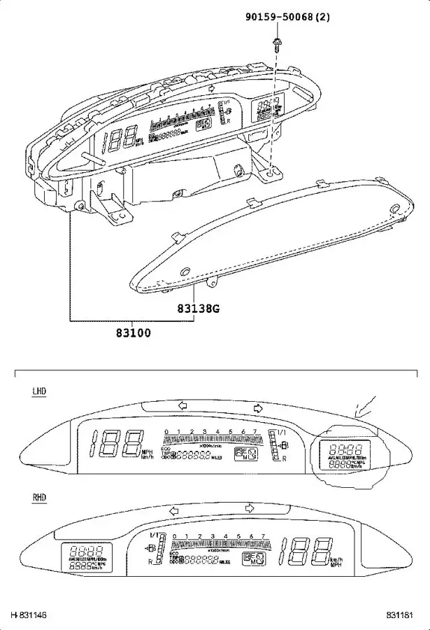
Here is the cluster and the clock on the right side
That is the one that I have. I just disassembled mine and hooked it up on my test bench to experiment with it. The clock and odometer are a separate assembly from the rest of the instrument cluster. Does anything at all display on the clock area of yours?
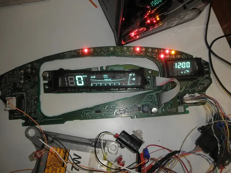
No nothing.Did you find something that can be replaced,or behind that LCD is a small electronic board.Maybe there is a malfunction,somethin broken or burned?
CTScottUSA, CT · Mar 29, 2013#24 Originally Posted by
skoya ↑ No nothing.Did you find something that can be replaced,or behind that LCD is a small electronic board.Maybe there is a malfunction,somethin broken or burned?
The small LCD (which is actually a vacuum fluorescent display) for the clock and odometer is a separate assembly, so that could be replaced as it may be the bad part. There are three separate circuit boards - The large main on, the one that the speedometer display is mounted to, and the "Core" board, which snaps to the back of the large board. The Core board contains the primary processor for the cluster and it has the EEPROM where the odometer data is stored. Unfortunately you can't buy the boards separately from Toyota, but if you can track down one from a wrecked Yaris, which has a cluster with the same part number, then you can either swap the clock/odometer display onto yours or you can swap your core onto it.
Yeah,but used clusters cost over 100$ on ebay,so it is a bit expensive.My dad is a electrician,so i wil disassemble the cluster and give him.Maybe he can find the problem.Anyway thank you for your response,i will notify you if i find something.
CTScottUSA, CT · Mar 29, 2013#26 Originally Posted by
skoya ↑ Yeah,but used clusters cost over 100$ on ebay,so it is a bit expensive.My dad is a electrician,so i wil disassemble the cluster and give him.Maybe he can find the problem.Anyway thank you for your response,i will notify you if i find something.
It looks like there is one driver for both the small VFD and the large one, so my bet is that it is the VFD itself. I have a couple of right hand drive Japanese digital clusters that I pulled apart a while back. I noticed that the small VFD is identical between the JDM RHD one and the European LHD one. I swapped one of the JDM ones into the European cluster and it works fine. I have a couple of them, so if you want to try one let me know.
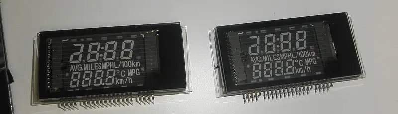
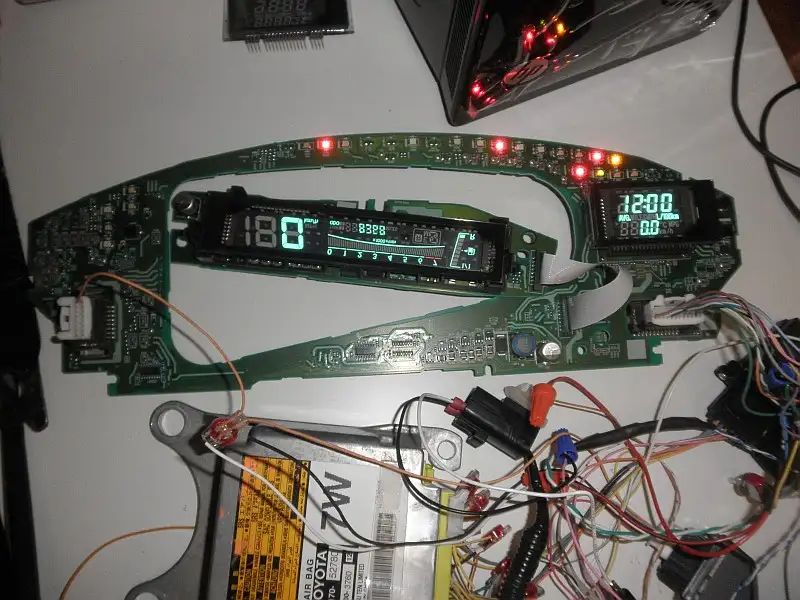
Ok,i am interested,tell me how we gonna do this.But i still need to be sure where is the problem with my clock.Give me few more days to test it,then i am going to let you know.
skoyaThread starterBosnia,Sa · Mar 31, 2013#28 Originally Posted by
skoya ↑ Ok,i am interested,tell me how we gonna do this.But i still need to be sure where is the problem with my clock.Give me few more days to test it,then i am going to let you know.
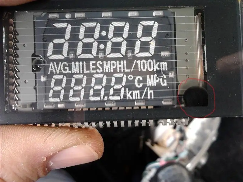
Here is the Pic of LCD.I was wondering this black spot in the right corner,is this ok.I mean I see on both of yours it is visible.Then again as i disassembled the speedo,it had also two of these marks,so i think this is ok.
That black spot does appear to be a normal part of how they manufacture the VFDs.
Since it is custom I can't find a data sheet for it. It would have been good if I could so that we could take some comparative measurements to determine if that is what is bad on yours.
skoyaThread starterBosnia,Sa · Mar 31, 2013#30 Originally Posted by
CTScott ↑ That black spot does appear to be a normal part of how they manufacture the VFDs.
Since it is custom I can't find a data sheet for it. It would have been good if I could so that we could take some comparative measurements to determine if that is what is bad on yours.
When I loooked at it,from each angle and side,i could not see any soldering error or something like that.It leaves now to test this small circuit board behind it.Then we shall see.
Originally Posted by
skoya ↑ When I loooked at it,from each angle and side,i could not see any soldering error or something like that.It leaves now to test this small circuit board behind it.Then we shall see.
The driver circuitry is actually on the bottom of the large board (where the large can shaped devices are). The small board on the back is the core board where the odometer data is stored and the main processor is located. I believe that that one is fine.
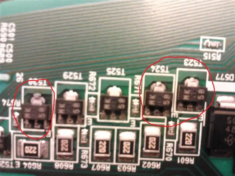
Ok Scott,here on this pic you can see these three transistors or whatever they are,seems to be burned.You can tell by their middle pins.I have isnpected them with ohmmeter,and the current flows on both sides instead of one.They are type MK 58.So when I turned the cluster on the other side,you can see clearly brown spots on this green pattern.Can you confirm that this could be the problem.You can see them right in the bottom middle section.
Originally Posted by
skoya ↑ Ok Scott,here on this pic you can see these three transistors or whatever they are,seems to be burned.You can tell by their middle pins.I have isnpected them with ohmmeter,and the current flows on both sides instead of one.They are type MK 58.So when I turned the cluster on the other side,you can see clearly brown spots on this green pattern.Can you confirm that this could be the problem.You can see them right in the bottom middle section.
That could be the problem or at least part of it. On mine all six of the transistors in that area check out correctly with the ohmmeter. I believe the 58 is a date code, since mine are all MK 61 on one cluster and MK 68 on another.
Originally Posted by
CTScott ↑ That could be the problem or at least part of it. On mine all six of the transistors in that area check out correctly with the ohmmeter. I believe the 58 is a date code, since mine are all MK 61 on one cluster and MK 68 on another.
Where can i buy these.Is there anything on ebay,or some another web page.
And i need some characteristics for this type.
Originally Posted by
skoya ↑ Where can i buy these.Is there anything on ebay,or some another web page.
And i need some characteristics for this type.
I am not sure. The MK alone is not enough information.
Hey Scott,can you please help me with this transistor.I could not find nothing with this code MK 58.It has to be another name for it.
CTScottUSA, CT · Apr 14, 2013#37 Originally Posted by
skoya ↑ Hey Scott,can you please help me with this transistor.I could not find nothing with this code MK 58.It has to be another name for it.
The number is just the date code. Unfortunately the MK portion has not been enough for me to figure out exactly what it is either. The only thing I can think of at this point would be for me to remove them off of one of mine.
I would be very grateful if you can do this for me,that's if you don't need them anymore.I need three pieces.
CTScottUSA, CT · Apr 15, 2013#39 Originally Posted by
skoya ↑ I would be very grateful if you can do this for me,that's if you don't need them anymore.I need three pieces.
I have one of the right hand drive ones that I just use for harvesting parts, so I can definitely ship you the three. They are tiny enough to be able to ship in an envelope as a first class letter, so shipping would only be $2.
Ok tell me what you need from me.
bs00944Ελλάδα · Oct 21, 2013#41@CTScott
I have also problem with the digital display clock... Suddenly the clock started to fade...and in half an hour it was complete black.
I think it is burnt.
Do you have any of these modules available?
I have a Yaris 2007 3d VVTi 1300.
Thanks in advance!
grgoEU, Croatia, Zg · Oct 4, 2015#42I have also problem with small display...
@skoya - did you fix your problem?
shepdKitchener, ON · Oct 4, 2015#43I would remove a good transistor from the board and meter it, along with figure out where each pin goes. This would help identify the base, collector, and emitter. After that, I'd assume they're pretty generic transistors and just replace it with one that has the correct pinout.
But you still run some risk doing that. :S
fpanczelRomania · Jun 6, 2016#44Hello All,
I have also problem with small display...
Somebody fix the issue?
BR,
Feri
GTJosNetherlands · May 28, 2018#45Hi all !
Same problem (for over a year now...)
Happy to find this forum/threat. Are there any real solutions yet ? Thank's in advance !
heinadriaanNetherlands · Jul 30, 2018#46I also have the same problem...
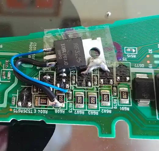
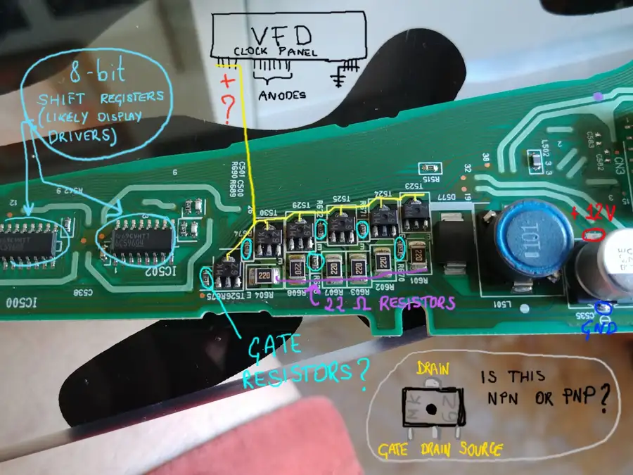
FrancescocyFlorence, IT · Sep 6, 2018#47I had the same issue on my 2007 Yaris (got it used on the cheap as my first car and there are some minor issues with it) the ICs in my unit are clearly burnt, they seem to be 6 BJTs or MOSFETs in parallel each with a 22 Ohm resistor to balance load. This part of the circuit seems to provide power to the cathode filaments in the fluorescent display and the parallel design makes it so that if one of the ICs gives up the ghost, the other 5 will follow soon after, since they have to split the load across 5 instead of 6. The clock is not an LCD, but rather a Vacuum Fluorescent Display (VFD), I could't find any information on this specific panel, but in general a voltage of about 2-3V is used on the cathode filaments; I first tried to replace the 6 ICs with a single powerful MOSFET, this kinda worked, but at 12V source to drain and you don't want that going to the filaments! Next step was to cut out the MOSFET and use a buck converter to provide steady 3V DC power. The screen turnes on, but the filament glows dimply orange and the numbers are dimmer than they should; probing the pins with the display on reveals that the anodes are only getting about 2V, if I understand this correctly, they should have a much higher voltage (10-30V), maybe some other part of the circuit is faulty? Another possibility is that the original power circuitry provided a negative bias voltage to the cathode filament respective to the anodes hence why my approach works, but dimly. At this point this is just speculation; I could disassemble the main VFD and probe that, but I'm too afraid of ruining it since I'd like to still be able to see how fast I'm going at the end of all this :)
If any of you has suggestions or can point out things I did wrong, I would be grateful!
I have same problem also with 2007 Yaris. I tried to repair solderings on fets and display now lights up and kinda works but fets are damn hot!
I will cotinue to work on issue. If anyone has figured out good fix for this please post some hints!
sven337France · Nov 4, 2018#49Might it be 2SB799 transistors? The marking ("MK") is consistent with that.
sven337France · Nov 24, 2018#50I solved the problem.
Looks like I was right, these are 2SB799 PNP transistors. I couldn't source them so I bought an equivalent BCX53 reference. I think it even has a somewhat higher nominal current so it should be better than the original ones.
I replaced the 6 transistors with these and everything works perfectly now!
Total time all included around 2h so it's a quick fix too.
My notes on how to disassemble it:
- take out the two side plastic parts (passenger airbag and warning button), these are just plastic clips so pull towards you
- remove the cover of the speedometer by pulling towards you (takes some force)
- remove two screws holding the meter in place
- pull the meter out, you need to rotate/warp the plastic a little
- go back to your desk and remove 2 screws at the back of the unit + the clips
- pull the back of the unit, be careful there is a mirror inside that is going to fall off
- disconnect the "mainboard" (10x10cm board, just pull it out it will disconnect)
- remove 1 screw on the front cover, then remove the front cover (many clips)
- remove the plastic cover of the main display (4 screws + 1 clip + rotate it)
- disconnect the ribbon cable of the main display and note what path it takes
- you can now pull out the power board/main board by removing the two clips and pulling towards you, which will disconnect the clock VFD
change the transistors, do everything in the opposite order, get the champagne out.
 Yarisworld