Replies continued
SumiHUNGARY · Jan 29, 2019#51 Originally Posted by
sven337 ↑ I solved the problem.
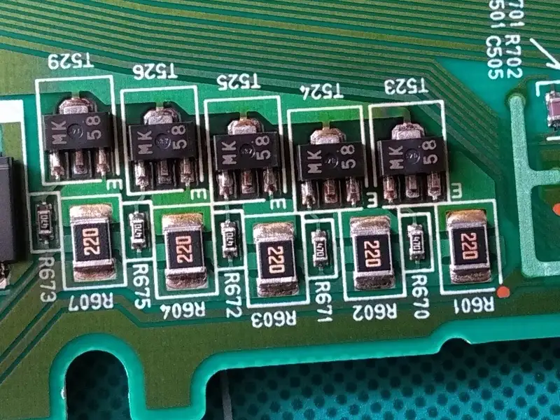
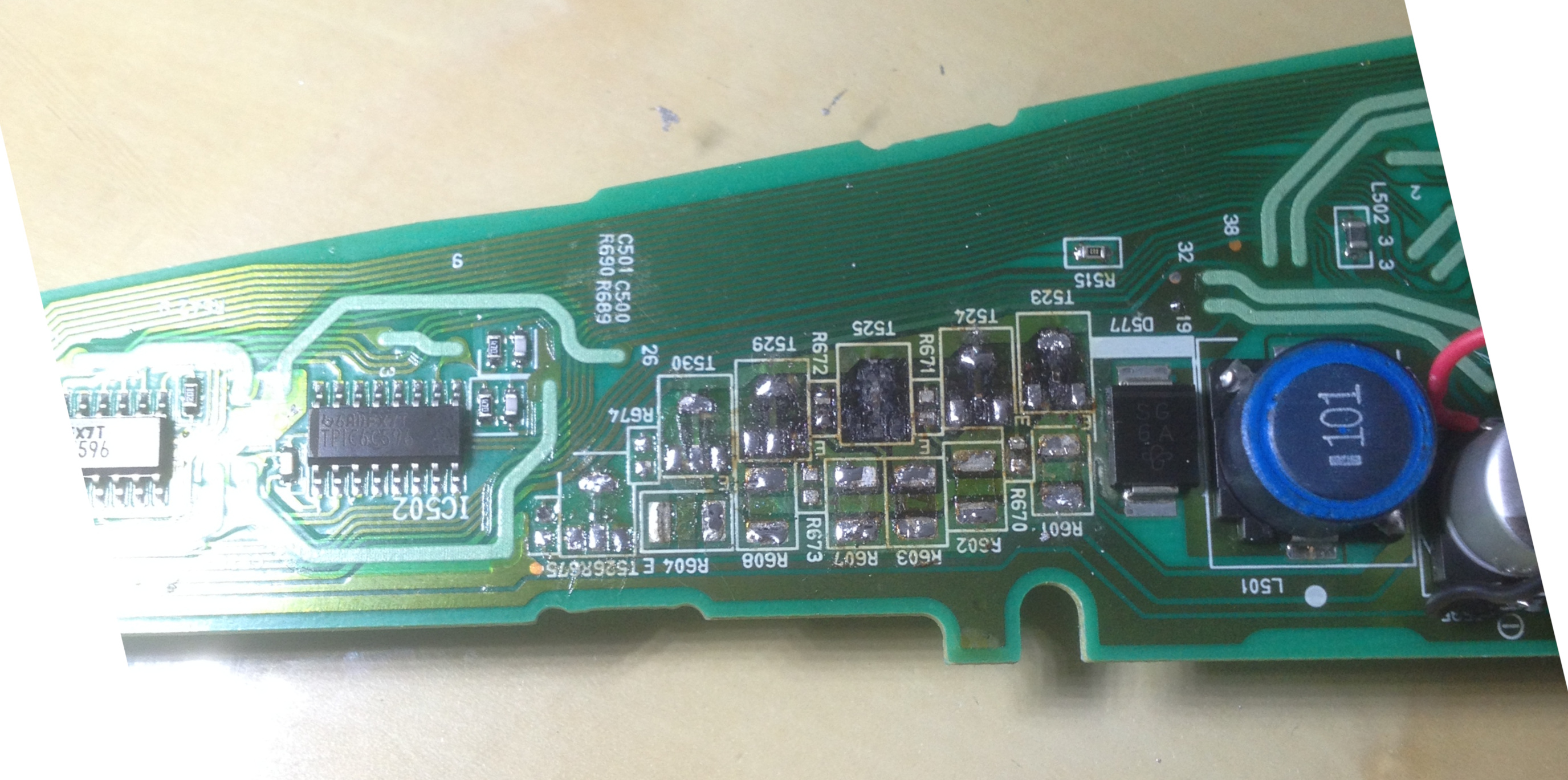
Looks like I was right, these are 2SB799 PNP transistors. I couldn't source them so I bought an equivalent BCX53 reference. I think it even has a somewhat higher nominal current so it should be better than the original ones.
I replaced the 6 transistors with these and everything works perfectly now!
Total time all included around 2h so it's a quick fix too.
My notes on how to disassemble it:
- take out the two side plastic parts (passenger airbag and warning button), these are just plastic clips so pull towards you
- remove the cover of the speedometer by pulling towards you (takes some force)
- remove two screws holding the meter in place
- pull the meter out, you need to rotate/warp the plastic a little
- go back to your desk and remove 2 screws at the back of the unit + the clips
- pull the back of the unit, be careful there is a mirror inside that is going to fall off
- disconnect the "mainboard" (10x10cm board, just pull it out it will disconnect)
- remove 1 screw on the front cover, then remove the front cover (many clips)
- remove the plastic cover of the main display (4 screws + 1 clip + rotate it)
- disconnect the ribbon cable of the main display and note what path it takes
- you can now pull out the power board/main board by removing the two clips and pulling towards you, which will disconnect the clock VFD
change the transistors, do everything in the opposite order, get the champagne out.
Could you please help me with the exact transistor needed?
These are the ones that I can source:
BCX 53-16 SMD, PNP, 1A/80V
Frequency: 145MHz
Packaging: SOT89
Collector current: 1A
Collector - emitter voltage: 80V
Power dissipation: 1.35W
OR
BC 869 = BCX 53, PNP, 1A/20V
Frequency: 60MHz
Packaging: SOT89
Collector current: 1A
Collector - emitter voltage: 25V
Power dissipation: 1W
Will any of these work?
Thank you in advance!
Put the champagne back in the bottle if you can, because the repair didn't hold. I haven't disassembled the device again to check what happened, but it sure looks like the transistors died. I do not understand why they would get seriously hot at all, this is a lot of power we're talking about... a display doesn't consume all that much.
Sumi, you want the 80V ones not the 25V ones. The 25V ones aren't BCX53.
TeeThreeSouth Africa · Mar 4, 2019#53Hello Sven, I was wondering if you found a solution to the transistors getting hot and burning out?
sven337France · Apr 24, 2019#54I do not know why my repair failed. I would assume the transistors are getting hot too, which makes me wonder if maybe the drive circuit is to blame. I wouldn't be able to fix that.
I'm planning to replace these transistors with P-MOSFETs, to see if they behave any better. They should generate less heat.
I've disassembled the clock again, and clearly the transistors were getting hot, and continued to burn off parts of the boards. A bunch of traces were torn apart when I removed the transistors. I've connected P-MOS the best way possible (had to use a few wires where the traces were gone), will test in a few hours and report back. Hopefully MOSFETs will have fewer thermal problems. Next step if *that* fails is to get 2 or 3 big MOSFETs instead of 6 small ones.
I do not have time to test more, but I went with PCP1302 MOSFETs and the result was a very very hot board after 3 minutes of displaying the clock. How much current does that thing pull?!
sven337France · May 4, 2019#55Just replacing the transistors doesn't seem to work (because they'll die again soon), so let's figure out what they're for exactly and take a higher level look: what is being implemented here?
The way they're connected, the six of them are basically in parallel and drive the cathode (the horizontal filaments) of the VFD. Their job is to get a steady 300mA through these filaments (full brightness, figure empirically found with a bench power supply).
In fact, you can remove the 6 transistors, and connect a constant-current power supply set to 300mA between the + and - (leftmost and rightmost) pins of the VFD, while it's plugged into the board - it will work normally.
I couldn't fully work out how the transistors were driven (=what their base is connected to), but it all goes back to the mainboard and a, on the power board, a pin that seems to be used to dim the VFD. I don't remember it dimming when turning on the headlamps but maybe that's actually what happens. I'm about to lose that feature anyway.
So, instead of trying to fix this broken cheap power supply with such a terrible efficiency that the transistors dissipate multiple watts (about 500mW each, which is not nothing for SOT-89), let's just replace it with something that works better. My theory for why the repair isn't working is that this design relies on the board helping to dissipate some heat, and when it's as badly burnt as mine it doesn't dissipate as well. Of course as soon as 1 transistor dies the rest will follow due to the parallel design. Crappy power supply design that saved maybe 2 bucks.
My plan is to find a buck module with a 2.5V output that I can use as a constant-current device, or if I can, add a series resistor to limit the current to about 300mA.
Then I'll rip out the 6 transistors and connect the buck module where I need it.
sven337France · May 5, 2019#56TeeThreeSouth Africa · May 6, 2019#57Thanks for the feedback Sven. I'm confident you may have found a lasting solution to the problem. I will look into the DC-DC converter - a nice neat solution.
Would something like the old LM317 work as well? I already have that in my box of spare parts.
If i set the LM317 to 1.5v this should be ok from what you have discovered from measurements.
Thank you for your effort and feedback.
sven337France · May 7, 2019#58 Originally Posted by
TeeThree ↑ Would something like the old LM317 work as well? I already have that in my box of spare parts.
If i set the LM317 to 1.5v this should be ok from what you have discovered from measurements.
Electrically it will work. Thermally I'm not so sure. LM317 is a linear regulator so in order to deliver 300mA@1.5V it will draw 300mA@12V and dissipate the difference, which is 3.1W.
The TO220 LM317 datasheet mentions a thermal resistance of about 40°C/W, so you're looking at 120°C over ambient temperature for a device with a maximum operating temperature of 125°C. That's why the original board had 6 transistors...
I wouldn't attempt it. A buck regulator has a better efficiency.
The LM317 is supposed to have thermal protection so it will likely shut down without burning too many things, but if your board is like mine any heat is too much heat.
Originally Posted by Kaanktm ↑
Could you please inform about the circuit connections on the board.
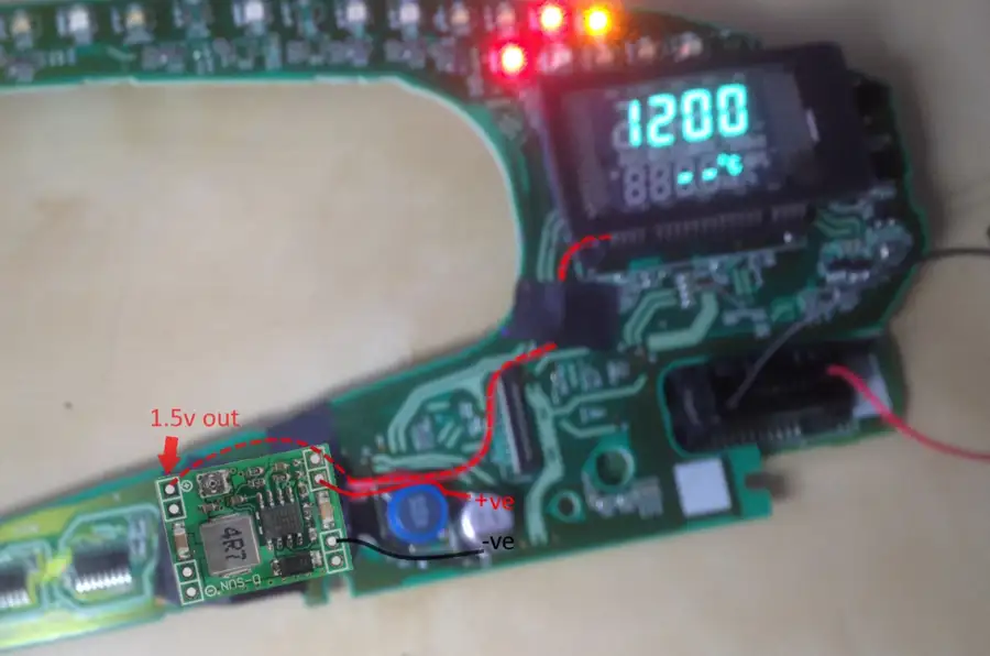
Are you asking about how to connect the buck module I had to the board? Assuming you have the same, but all buck modules work the same way anyway, you have three leads to connect: Vin, Vout, and GND.
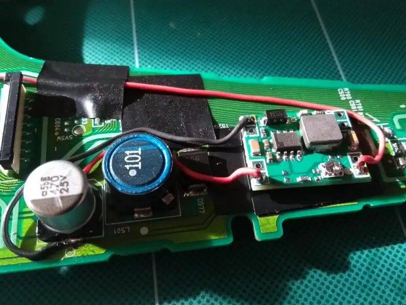
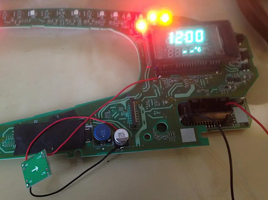
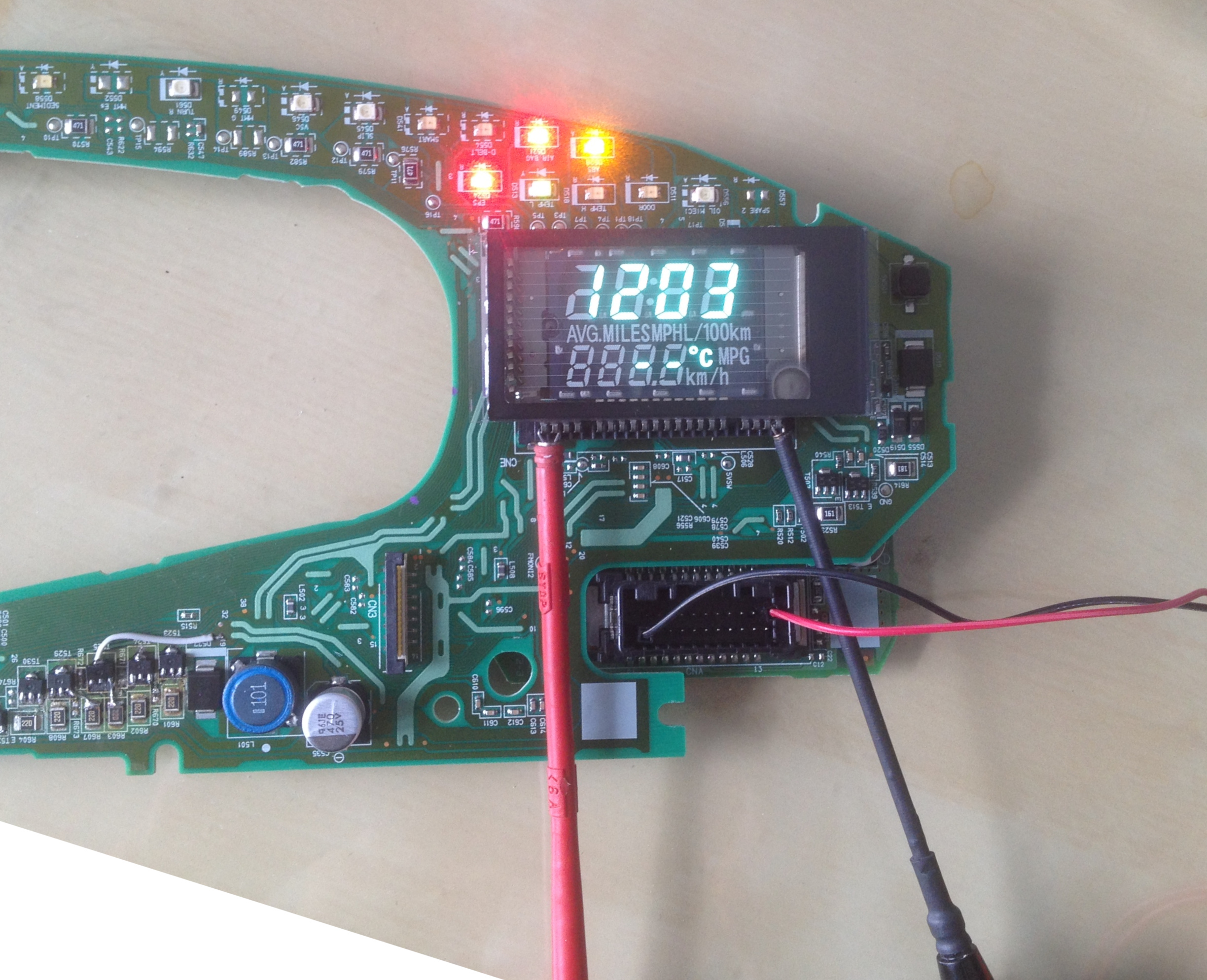
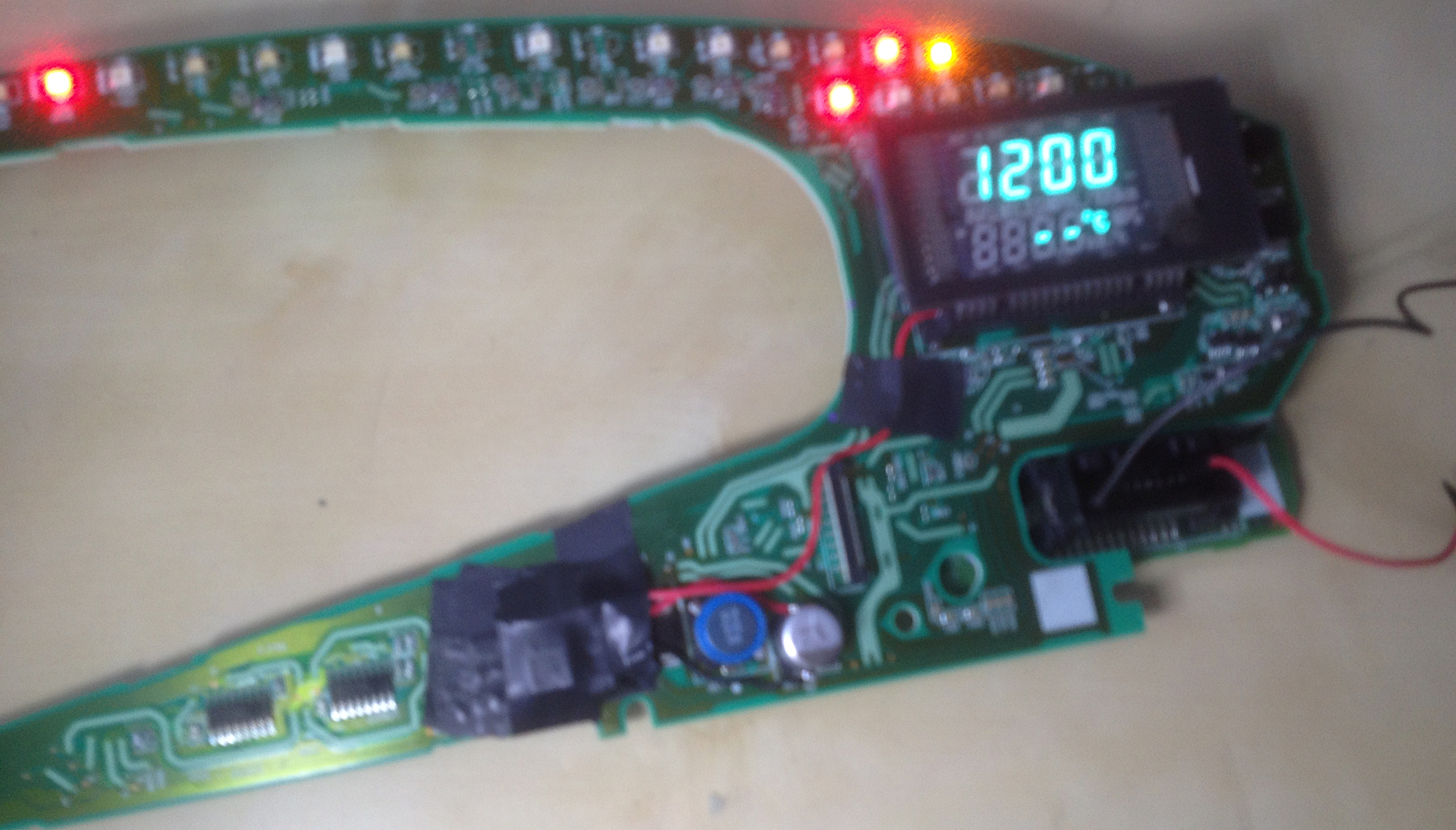
If you look at my very blurry (sorry..) last picture, you can see two red wires and one black wire (at the bottom)*come out of the module. The black wire is GND, and I've taken it at the GND of the capacitor that is next to the blue inductor.
Vin was the + of this capacitor (I think the capacitor/inductor/diode here are an input filter, all I really care about is that there's a constant 12V power supply available there and it was the input of the NPN transistors).
Vout is the leftmost pin of the VFD connector (all 4 left pins are connected together).
I hope this helps you
Has this repair held out for you so far sven337 ?
sven337France · May 12, 2019#61Because I got the question in private multiple times:
- buck modules are not insulated so they have a single ground - no need to connect both ground wires, any of the two will do
- yes, the repair is still holding out, and I've got a good hope that it will hold forever because I think it's "clean"
Do note that you need to remove the transistors (and while you're at it the emitter and base resistors to make room) before connecting the buck module.
Thanks sven337,
So the wiring is like this
The 12v feed to the module derived from smd capacitor c535 (470uf/25v) and the dc,
aprox 1.5v out (adjust via potentiometer) goes to the left hand pin 1 of the VFD.
Many Thanks again for your help.
Correct
sven337France · May 14, 2019#64That is correct, my instructions didn't cover it but the VFD is held in place inside the white plastic part by its top, you have to slide the top first and then press down the part with the pins to get it back in the white plastic part.
But, you don't actually need to remove the VFD from the white plastic part for this fix, what you need to do is separate the white plastic part from the board which my instructions do cover, albeit without drawing attention to the need to ensure that the VFD pins are correctly connected upon reassembly (it's just a matter of pressing hard on the VFD itself).
Hi all,
I have the buck module on route from China and hope to complete this modification/repair in the next few weeks.
Can someone explain what this fragile VFD white plastic frame looks like.
I take it that we are dealing with the small VFD and is this "frame" part is the frame which holds the whole clock/warning light pcb to the rest of the instrument assembly ? Hence "many clips" in svens dis assembly guide.
I am looking on this thread for a photo of the frame to identify it but all i can see is a small black frame /surround fitted to the small clock VFD.
Thanks guys.
Great fix btw !
sven337France · May 20, 2019#66Don't worry about it. Can't miss it when you disassemble, it's the largest plastic part and the only one colored white. And there's nothing to be careful about really, just to know that when you separate it from the black part at its back, it will disconnect the VFD, so don't pull sideways. And after you clip the black part back on (don't push sideways...), you'll need to push on the VFD (it's glass, you can push hard) to make sure its pins are connected.
Thanks sven337, I see the white part now, it is pictured in post #48 of this thread, it looks like a support frame to hold the main pcb board.
From the descriptions the white frame holds the VFD display module and the main pcb and when you separate the frame from the main PCB the VFD stays in place on the white frame as it has a slot and a pair of clips to hold the VFD module.
Then its a case of unclipping the VFD from the frame and plugging it into the bare socket for testing/wiring up. Plugging in the VFD provides a load so that the buck module output voltage can be adjusted properly (with a load attached).
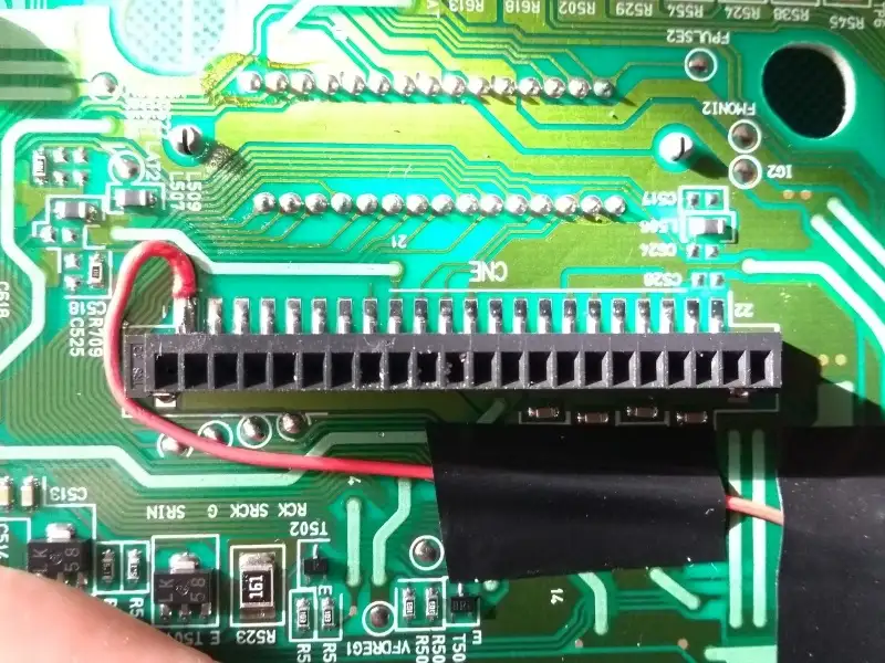
I take that the buck output wire is stripped back a few mm at the VFD socket end and the bare end is pushed into pin #1 of the socket receptacle? (The male pin of the VFD holds the wire in place when the VFD is placed back onto the white frame and its all pushed back together).
Did you have any diffculty in removing the SMD components ? Lead free solder is a pain sometimes.
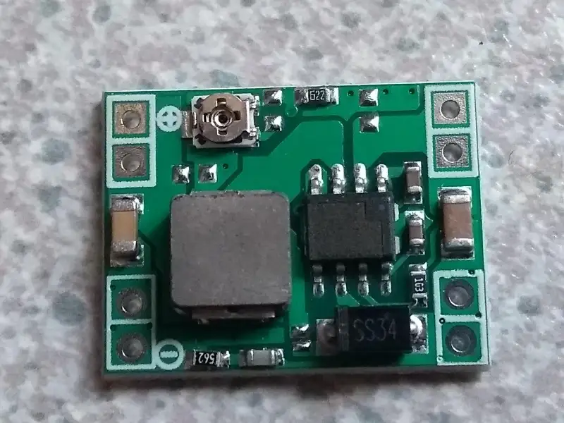
I can see this as a really good fix as the MP1584 based modules run at much lower temperatures than others. 👍
Still waiting for my package from China (buck module)
sven337France · May 30, 2019#68It's a buck module, not a linear power supply, you can adjust it without a load.
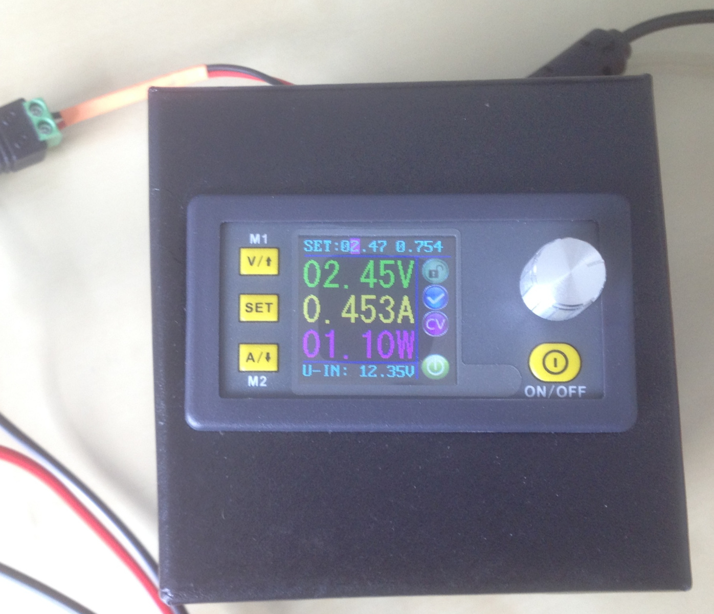
The VFD is only useful for testing, if you're doing my repair you don't need it you just need to set up the buck module for about 1.5V.
Removing the SMT components is easy. Chisel tip, 30W or more, add a bunch of leaded solder, heat up like crazy (you don't care you're removing everything) and the transistors will slide right off.
As for the VFD socket, I actually soldered the output lead of the buck module to the base of the VFD connector. Not soldering sounded like a potential issue with vibration.
Right hand drive model repaired, thanks to sven337 for the instructions.
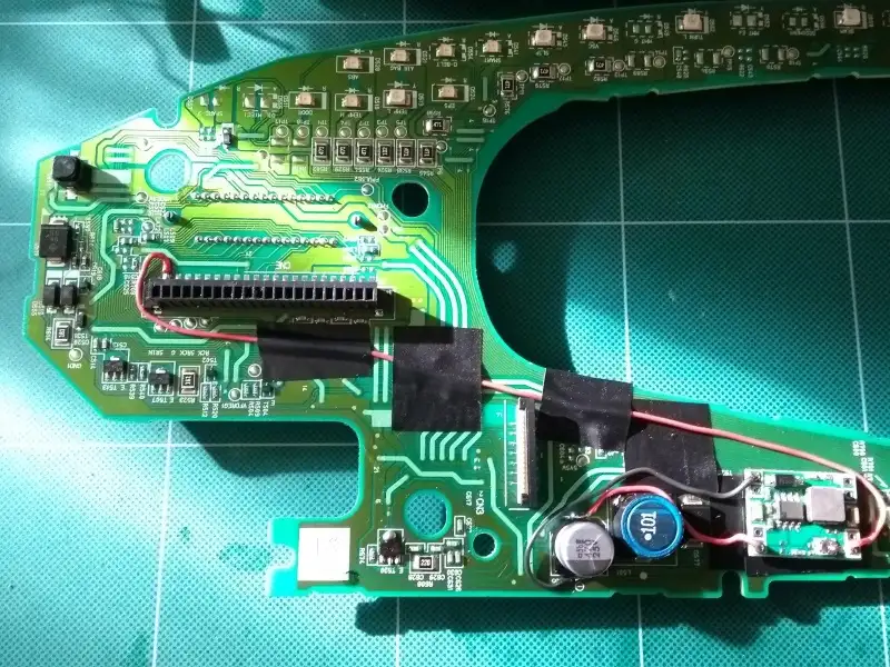
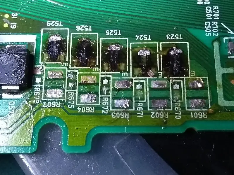
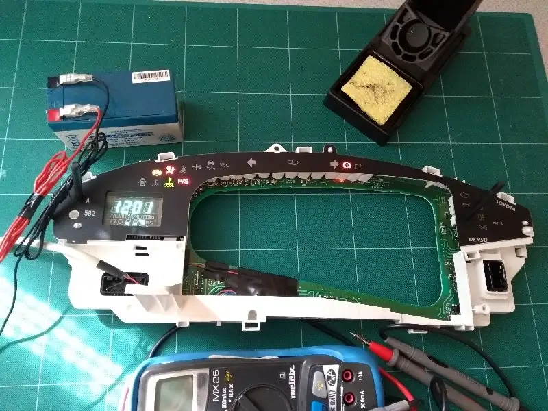
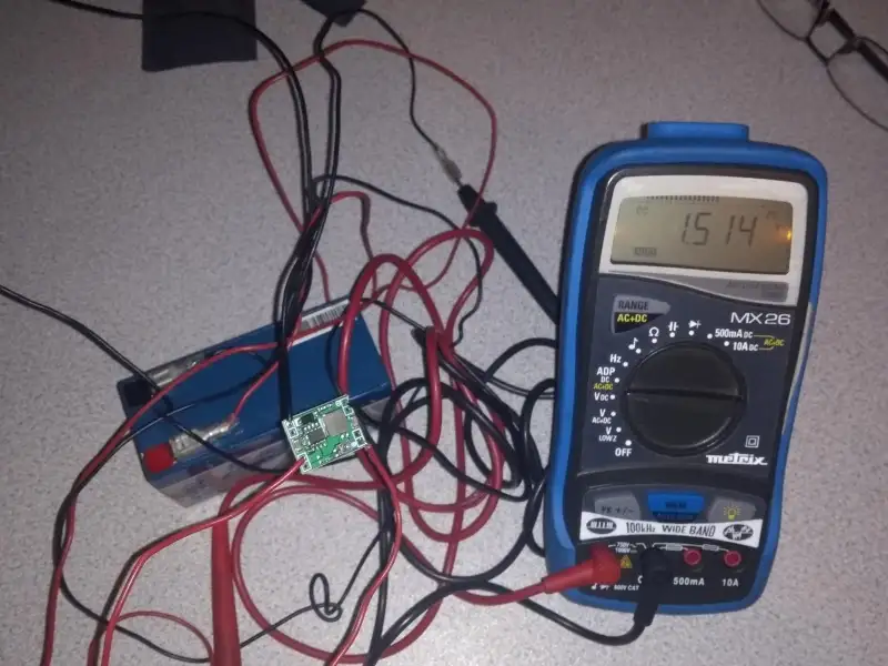
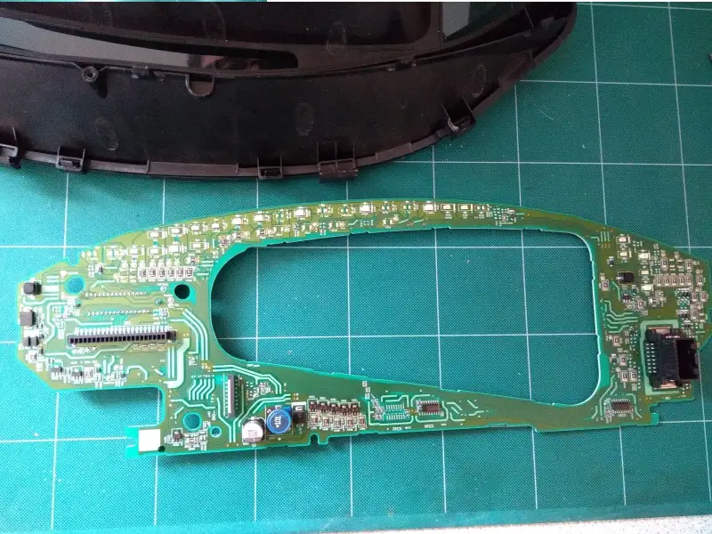
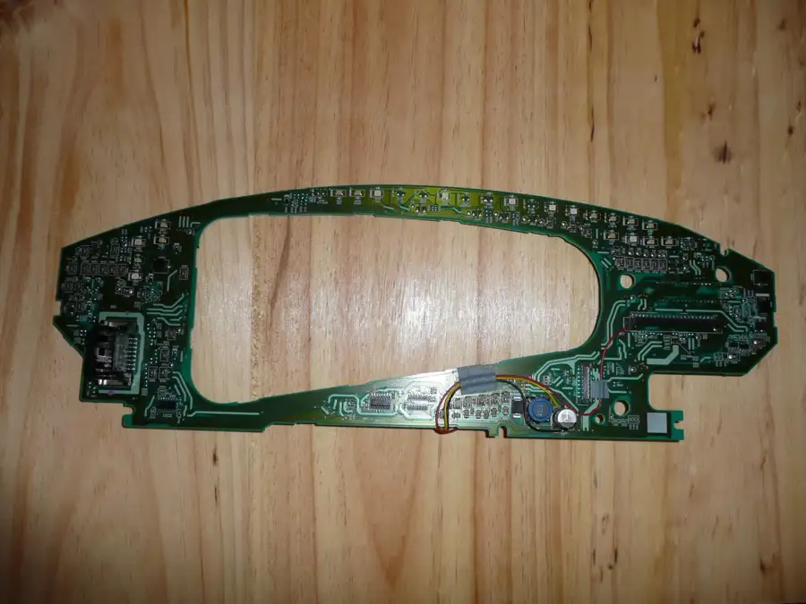
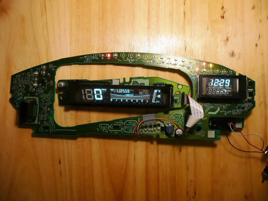
Photos of MP1584EN device, testing with DMM to obtain correct output of 1.5v, more photos of the existing transistors and after removal (a few pads came off in the process) , close ups of buck regulator in situ and wiring to pin 1 of VFD connector.
I disconnected the battery negative terminal before removing cluster.
Used a 12v 1.2ah battery from commercial intruder alarm panel as poor mans lab psu for testing.
I noted that there were 5 transistors not 6 for my model.
That ribbon cable is a right PITA to get back in to the slot and close the latch on the connector !
Sorry if the photos are in the incorrect order.
Thanks again sven337 !
Thank you for the excellent pictures that will, no doubt, help people implement the fix.
NOLFKaliningrad(Russia) · Aug 13, 2019#71Sorry but i can find dashboard pinout, can you post it for me. I can't test me dash, i don't no where is positive and negative.
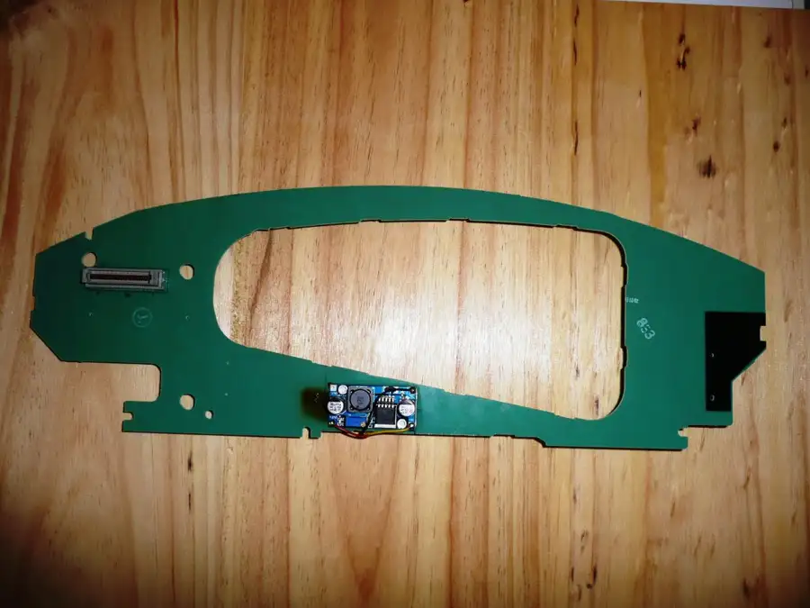
sven337France · Aug 14, 2019#72sven337France · Nov 16, 2019#73Someone asked me to repair their clock, I took a better picture of the fix + the test setup.
Is there anyone out there who managed to fix it by replacing the transistors? I'd need the dimming feature.
SumiHUNGARY · May 18, 2020#75Okay, so I've pulled it apart today and resoldered the transistors, as mentioned by a comment on sven337's page. I don't know if this will last, because when I start the car the clock display comes on pretty slowly, which tells me that something isn't quite right, although I don't remember how it used to be. But at least it works for now.
@sven337, do you think that there is any risk of fire when the transistors die? I can imagine there is quite some heat if it's enough to make the PCB turn brown on the other side.
bubinioGreece · Jul 5, 2020#76Hi guys,
I tried sven337 solution but with 1,5V the clock is not bright at all. When i adjust it at about 2,7V to be brighter then the red lines appear. When the lights are turned on, the clock is not readable!
Great work though for sven337 and all the rest!!
SumiHUNGARY · Feb 15, 2021#77 Originally Posted by
Sumi ↑ Okay, so I've pulled it apart today and resoldered the transistors, as mentioned by a comment on sven337's page. I don't know if this will last, because when I start the car the clock display comes on pretty slowly, which tells me that something isn't quite right, although I don't remember how it used to be. But at least it works for now.
@sven337, do you think that there is any risk of fire when the transistors die? I can imagine there is quite some heat if it's enough to make the PCB turn brown on the other side.
Died today again.
Any ideas how to do the boost converter mod with retaining the dimming feature?
Hello,
As others on this thread, I have the clock/temperature/ average consumption display problem.
The thing is that I just bought the car second hand 2 weeks ago. I didn't see that missing display until I drived it several days, asking myslef how possible it was for a car not to have a clock ( I use to have the Yaris 2004 before, that has all those features)
The person that sold it to me ( herself 2nd byuer) said that she never paid attention to that and that it was surely already out when she bought the car 5 years ago ).
Anyway, I've found this thread via the french page of sven.
The problem is Im not equiped (and talented) to start trying taking all those pieces out :/
I saw on the thread that you can find the full part with the screen etc but it is 150 € !
My questions are :
- is there a way to find just the electronic panel , cheap, and to replace it ?
- how expensive would it cost to me if I go to a toyota garage and ask them to repair it ?
Also, if you know someone in Belgium that would accept to do the work for me in exchange of of a good price, Im interested :)
Oh, and I also have the "turning button" to change from outside/recycling air" that is blocked on the " outside air" , but I hope it is just a plastic thingy blocked behind the n panel, nothing electronic here)
Thanks a lot !
Regards,
Dreamer
mimikSweden · Apr 10, 2022#79Is it possible to replace the old faulty cluster with a second hand unit that works?
Or will that mess up ODO etc?
almamaterPT · Jun 27, 2022#80Well, my Yaris 2006 had the same issue 1 month ago, yesterday i decided to do the procedure mentioned here, thanks to Sven337 !!
All worked Now, i decided not to remove the transistors, i just added the MP1584EN, and in this way, the dim functionality continues to work..
If anyone needs pictures i can post them, i took some.
Thanks!
brugal67italia · Sep 26, 2022#81could you send me the photos of the modification?
MarafadoPortugal · Mar 14, 2023#82 Originally Posted by
almamater ↑ Well, my Yaris 2006 had the same issue 1 month ago, yesterday i decided to do the procedure mentioned here, thanks to Sven337 !!
All worked Now, i decided not to remove the transistors, i just added the MP1584EN, and in this way, the dim functionality continues to work..
If anyone needs pictures i can post them, i took some.
Thanks!
Hello.
Another one with the same problem.
Thanks to sven337's posts, I'll try to follow his procedures as well.
In your case, you decided not to remove the transistors. You say that this way the variable brightness functionality remained functional.
Can you confirm that everything is back to normal after the repair and no more problems have appeared?
I'm thinking of a more complex repair, but just in case it's justified!
Thanks
Here is the solution I implemented.
Originally Posted by
Marafado ↑ Here is the solution I implemented.
Hi mate! Can you give more details about the module?
Please, I'm looking for the wiring diagram for the connector.
magicyarisspain · Mar 17, 2026#86Muchisimas gracias a sven337 por la información y a adsb por las imágenes proporcionadas sois unos putos Top Globales y unos máquinas.
Gracias a este foro y toda la información que hay aquí intentaré arreglar la pantalla del yaris y sino lo consigo ha sido un placer enloquecer junto a ustedes
javito81España · Aug 1, 2026#87 Originally Posted by
sven337 ↑
Thank you so much, I was able to fix my watch thanks to you, best regards. :arco:
 Yarisworld