PatrickJohnsonOriginal postMurfreesboro, TN · Jul 19, 2009#1So, I was tired of keeping up with my garage door opener. I had stashed it in my driver's side glove box for the last year with some velcro, but i'm too lazy to keep opening up the glove box to open the garage. So, I dismantled my garage door opener to see how it works and see if I can rig up a nice, stock looking button on my door to use. It was easier than I thought it would be...
Here is my garage door opener dismantled. Although openers vary, almost all of them use the same basic topology: a momentary switch closes a circuit which triggers the signal sent to the opener to open/close the door. As a bonus, the board for the opener switch has pads for more switches right on the board. The pictures were taken after I had already soldered wires to the switch pads:

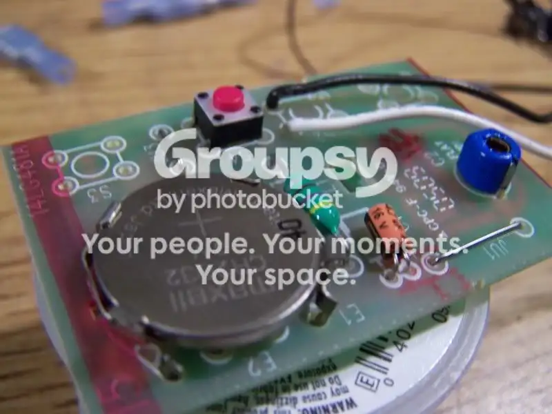
I then wired up the switch:

A quick test.... SUCCESS!
so then i started to decide where to mount the switch. The optimal place IMHO is in the push-button start button cover. But I had already mounted my cruise control switches there, so I opted for another good location, the forward most door sill trim piece:


Works like a charm! I used the same popular black momentary switch we all seem to be buying from radio shack. I drilled the hole just slightly too big, so I used a thin nylon washer I had lying around (after painting it flat black) to mount the switch, and i think it looks COOL...
I tucked the board for the opener down in between the factory door panel pad and the door panel.
Replies 37
rningonfumesSoCal · Jul 19, 2009#2Nice and clean!
yaris-meAnaheim, CA · Jul 19, 2009#3Good idea.👍
counterfiendDallas, tx · Jul 19, 2009#4thats is awesome, couldnt you wire this into a power source in the car so you could null out the battery? use some resisters to bring it down to a propper level so you wont have to worry about doing anthing
IsLNdbOiLas Vegas, NV · Jul 19, 2009#5Nice.
I've been looking for a way to hide the garage opener too. I have to wait though. Not sure how much longer I'll be staying at this house. New house will probably have a newer garage opener model and remote.
eTiMaGoBangkok, Thailand · Jul 19, 2009#6hahahaha nice! I've been meaning to do this for ages but too lazy 😁 And mine runs off a lil 12V battery, even better...
Sodium DuckWestern Mass. · Jul 19, 2009#7Can you post pictures of your cruise control too? (sorry to get off topic)
PatrickJohnsonThread starterMurfreesboro, TN · Jul 19, 2009#8the cruise control is pictured in the DIY cruise control thread... search is your friend.
At some point I'll probably power it from the car, but mine is a 3 volt, so I have to build a little voltage divider circuit first. One day when i'm bored...
RevssonSoutheast Wisconsin · Jul 19, 2009#9That's a nice mod.
How about an antenna to extend the range? (might not be legal) 🤷
I live in an apartment and don't think the landlord would appreciate me
modifying the door opener. 🙁
nickhjortOneida, NY · Jul 20, 2009#10There is a very popular garage door opener mod on my Yamaha R1 forums. It does exactly the same thing, but ties the switch into the high beams. So all you have to do is pull up, flash your highs and you're good to go. Flash once again to close it behind you :) Check it out. It has the 3V power source converter plans too...
HIGH BEAM GARAGE DOOR OPENER MOD Originally Posted by
Revsson ↑ That's a nice mod.
How about an antenna to extend the range? (might not be legal) 🤷
I live in an apartment and don't think the landlord would appreciate me
modifying the door opener. 🙁
Don't they sell universal garage door openers? Or you could just pick up a replacement remote from the manufacturer.
those switches are fine in size, but they are on/off toggles, you need momentary switch
CTScottUSA, CT · Jul 24, 2009#14IsLNdbOiLas Vegas, NV · Jul 24, 2009#15 Originally Posted by
PatrickJohnson ↑ those switches are fine in size, but they are on/off toggles, you need momentary switch
Cool. What about these?
http://www.frozencpu.com/products/6512/ http://www.frozencpu.com/products/6099/ Originally Posted by
CTScott ↑
Cool. How would I use that? It's kind of large. I'm guessing I'd have to gut it and set the switch to 3V then make the connection from one of the car's 12V power wires to the 3V battery receptacle on the garage door opener then just connect the same 12 power wire from the car to the 12V LED on the power switch to get the illumination.
Would a power wire going to one of the power door locks or window switches work with this?
Originally Posted by
IsLNdbOi ↑ Cool. What about these?
http://www.frozencpu.com/products/6512/ http://www.frozencpu.com/products/6099/ Cool. How would I use that? It's kind of large. I'm guessing I'd have to gut it and set the switch to 3V then make the connection from one of the car's 12V power wires to the 3V battery receptacle on the garage door opener then just connect the same 12 power wire from the car to the 12V LED on the power switch to get the illumination.
Would a power wire going to one of the power door locks or window switches work with this?
Correct on the wiring of the power adapter. With the plastic removed, the circuit board would be very small.
Those switches would be fine.
You'd probably want to grab two separate power sources. Ignition switched power (or maybe dimmer output) for the LED and always on for the opener supply.
Thanks CTScott. Do you know offhand if there are ignition switched and constant 12v power wires going to the power door locks and windows switches?
The power door locks work even when the key isn't in the car (if you're in the car and press the door lock switch when the car is off, the doors still lock / unlock). The power window switches don't though.
PatrickJohnsonThread starterMurfreesboro, TN · Jul 24, 2009#18 Originally Posted by
IsLNdbOi ↑
YES! Those will work and look great. You'll just have to run a little power to it to run the illumination. If you are going to use the spot i did to mount it, it should be easy to tap the illumination off the dimmer rheostat so that it brightens/dims with the other interior lights
Cool. How would I use that? It's kind of large. I'm guessing I'd have to gut it and set the switch to 3V then make the connection from one of the car's 12V power wires to the 3V battery receptacle on the garage door opener then just connect the same 12 power wire from the car to the 12V LED on the power switch to get the illumination.
Would a power wire going to one of the power door locks or window switches work with this?
this is a better (though more expensive) solution:
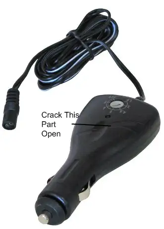
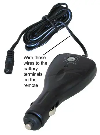
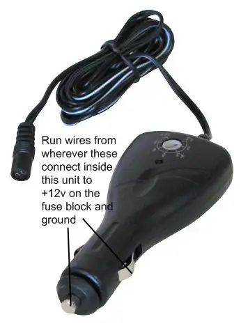
http://www.dimensionengineering.com/AnyVoltMicro.htm but if i were to get the one CTScott posted, I would crack open the cig plug part (after switching it to 3 volts) and mount that board near the garage door opener board on the inside of the door. then I would run wires from the power points that went to the plug connections down to a +12v spot on the fuse block.
Then clip the wire part of the power board to a suitable length and wire it to the battery pads on the open remote board. make sure to remove the battery on the remote board, or else you will be sending 6 volts (2 3 volt supplies in parallel) and will likely mess up the opener.
Thanks again guys. PatrickJohnson, that micro-converter is nice. I looked at the PDF manual and it says that it does 3.3V. I didn't see 3V listed. Would this still work?
I'm guessing one pin is for ground, one pin is for input voltage (the 12V from the car) and the third pin is for the output / converted voltage (3V out to the garage opener).
Edit:
Nevermind, missed a part of that PDF file on their site.
CTScottUSA, CT · Jul 24, 2009#20 Originally Posted by
IsLNdbOi ↑ Thanks CTScott. Do you know offhand if there are ignition switched and constant 12v power wires going to the power door locks and windows switches?
The power door locks work even when the key isn't in the car (if you're in the car and press the door lock switch when the car is off, the doors still lock / unlock). The power window switches don't though.
You can grab switched power from the gray wire on the power window master switch, constant power at the brown wire on the lock assembly, and ground at the white with a black stripe on the power window master switch. Just make sure you add a fuse from those to the opener and LED.
So I add one fuse b/w the switched power and the LED and one fuse b/w the constant power and the voltage converter?
What size and type of fuse and how do I add these fuses?
PatrickJohnsonThread starterMurfreesboro, TN · Jul 24, 2009#22hmm, yes, i'd like to know too. the current draw doesn't seem to warrant a fuse... maybe i'm missing something though, CTScott is the Electrical Engineer! 🙇
CTScottUSA, CT · Jul 24, 2009#23The window and door circuits are high power circuits. The fuses would prevent fire in the door in the event of a failure of the door opener or its wiring. I would tap the power wires mentioned and use an inline fuse. I would go with a 1 amp fuse on each.
When you tap a high current circuit, the fuse you add is not to protect the circuit you are tapping, but rather to protect what you are adding with an appropriately sized fuse for the current draw of the device / minimum gauge of wire used.
IsLNdbOiLas Vegas, NV · Jul 24, 2009#24CTScottUSA, CT · Jul 24, 2009#25Exactly.
IsLNdbOiLas Vegas, NV · Jul 25, 2009#26Ok, I've decided on this switch (goes with the other black buttons for the door locks and windows):
http://www.frozencpu.com/products/6099/ The silver version of this switch:
http://www.frozencpu.com/products/1904/ has this note:
"
Note: The LED runs on 3.4V DC. You will need a resistor in the line to power the LED from either your motherboard's 5V DC output or your Power Supply's 12V DC output. You can run the LED directly off of the motherboard's 3.3V LED headers without any resistor.
We were informed that the correct resistors for the switch's LED are the following:
12 V DC source: 420 ohms
5 V DC source: 70 ohms
"
So in addition to the 1amp fuses, we need resistors too (if the black version of the switch is identical to the silver one other than color).
What type and kind of resistor would we need for this and where in the line would we put it? Would we need more than one resistor or one for each (one for the LED and one for the switch to micro-converter to garage opener)?
That's strange that the two are identical except for the anodizing, and yet one is listed as having a built-in resistor and the other not. If the black one requires the resistor, it will go in line with the power supply to the LED. So, from the +12V switched power you will have the fuse, the resistor, and then the LED contact on the switch.
Only the LED needs the current limiting resistor, so you only need one.
IsLNdbOiLas Vegas, NV · Jul 27, 2009#28I emailed FrozenCPU about the switches. This is their reply:
"
Both versions are now the newer ones following the specs you saw on the black switch. They are all now compatible with 12V LED source and need no resistors.
Hope that helps!
"
PatrickJohnsonThread starterMurfreesboro, TN · Jul 27, 2009#29sweet. 20 buck switch for a 3 dollar mod, but i think i might get one of those.
IsLNdbOiLas Vegas, NV · Aug 4, 2009#30I found a nicer looking switch that matches the color of the other buttons / switches on the door and has amber / orange illumination:
http://www.performance-pcs.com/catal...ducts_id=23263 It has a 3V LED though. The battery for my garage opener is also 3V.
Since both are 3V, could I connect both to the vOut of the micro DC converter? Or would I need two of these converters (one for the LED and one for the garage opener's power)?
Also, what would I need to do to have the LED in this new switch dim with the other interior lights when I turn the dimmer dial?
Originally Posted by
IsLNdbOi ↑ I found a nicer looking switch that matches the color of the other buttons / switches on the door and has amber / orange illumination:
http://www.performance-pcs.com/catal...ducts_id=23263 It has a 3V LED though. The battery for my garage opener is also 3V.
Since both are 3V, could I connect both to the vOut of the micro DC converter? Or would I need two of these converters (one for the LED and one for the garage opener's power)?
Also, what would I need to do to have the LED in this new switch dim with the other interior lights when I turn the dimmer dial?
All you would need to drive the LED off of 12V is an ~ 680ohm resistor in-line with it. With that in place, you could then connect it to the output of the dimmer rheostat to have it dim with the rest of the lights.
Got the AnyVolt Micro. Was going to test it w/ a PC power supply and the garage door opener, but it turns out you need a multimeter to see what voltage the AnyVolt Micro is putting out.
upgradedyarisHere · Jan 1, 2010#33I bought mine today and installed it already. The button is mounted in the same panel as the PW switches. (right below the rear window buttons)
I will do this to the other car too since I bought 2 switches.
Toy YarisMelbourne , Australia · Mar 14, 2010#34Can i tap into the high beam wires my remote has a 12v battery do i need relays , resistors?? can i get power from the high beams???
kazama82Malaysia · Mar 15, 2010#35why dont tap at dimmer light constants 12V and add 1kohm resistor to lower the 12V to 3V input..that's what i do for my handle 3V LED
Toy YarisMelbourne , Australia · Mar 15, 2010#36will be removing the led as I wont be seeing it, i dont want a switch in the car so i was thinking of tapping in the high beam wires. similar to flash2pass
smell my fingerIllinois · Mar 16, 2010#37very nice! now all I got to do is figure how to hook up my flux compasitor.
ShinareOklahoma City, OK · Oct 8, 2010#38Just did this using the same radio shack black momentary switch in the same location. I wanted to hard wire it into a switched 12v source but I could not find the required electronic components to step the 12v down to 3.3v at my local Radio Shack, namely the LM317 Adjustable Linear Voltage Regulator and the 100 and 150 ohm resistors as indicated would be necessary in the High-beam motorcycle thread. They Had an LM317T regulator but did not know if that was the same, but still not the right resistors anyway. So I just wired it up to the little battery from the remote. I guess when it goes dead I can replace it but really didnt want the button to work unless the ignition was on. Works tho and I'm happy. First real mod to my yaris. :) (Since I didn't do the tint but had someone else do it, heh.)
 Yarisworld